Contaminated cuvettes silently corrupt fluorescence data. Residues as thin as a few nanometers can elevate baseline noise, distort emission peaks, and invalidate hours of experimental work.
Proper cleaning of a quartz fluorescence cuvette is not a peripheral housekeeping task — it is a fundamental requirement for spectroscopic accuracy. This article covers every stage of the cleaning process, from contamination identification through drying and storage, providing laboratory personnel with the complete technical framework needed to maintain cuvette performance across its full service life. Each section is grounded in established spectroscopic principles and practical protocols validated across fluorescence, UV-Vis, and biochemical research environments.
Fused silica cuvettes are precision optical instruments. Treating them with the same rigor applied to instrument calibration is what separates reproducible data from unreliable measurements.
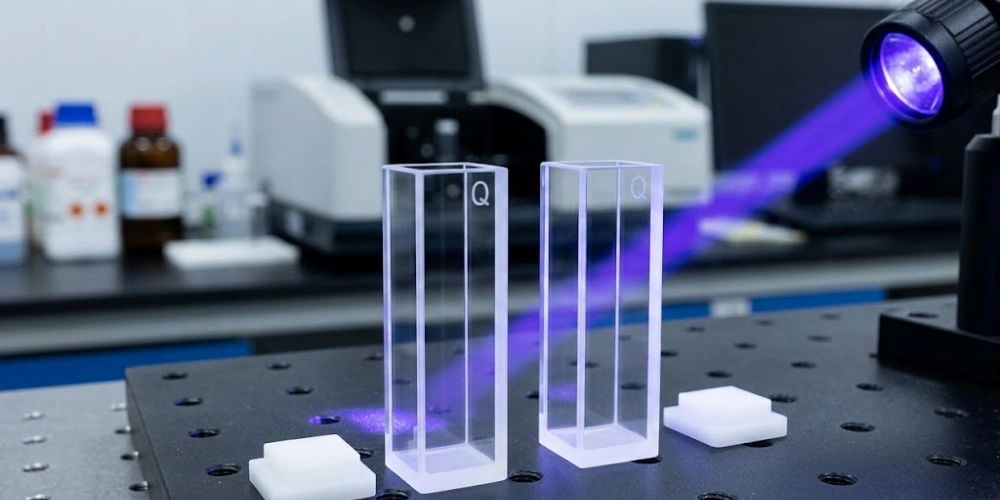
The Optical Sensitivity of Quartz Fluorescence Cuvettes
Among all variables that affect fluorescence measurement quality, the physical state of the cuvette walls is one of the most consequential — and one of the most frequently underestimated. The extraordinary UV transparency of fused silica, which makes quartz fluorescence cuvettes indispensable for photophysical research, simultaneously makes them acutely vulnerable to surface contamination. Because the material transmits light across a range of nearly 170 nm to 2700 nm without significant self-absorption, any extraneous substance on the optical surface — whether organic, inorganic, or biological — becomes directly involved in the optical pathway.
UV Transparency and Why Surface Films Matter
Fused silica transmits ultraviolet radiation at wavelengths where borosilicate glass and acrylic absorb completely. The practical transmission window of high-purity fused silica extends from approximately 170 nm to 2700 nm, covering the full excitation and emission range used in fluorescence spectroscopy, including deep-UV applications at 200–250 nm that are inaccessible with standard glass cuvettes.
This exceptional transparency creates a critical consequence: any film deposited on the optical walls is simultaneously illuminated by the excitation beam and interrogated by the emission detector. A protein film with a physical thickness of just 5–10 nm can produce measurable autofluorescence when excited at 280 nm due to intrinsic tryptophan and tyrosine residues. Even sub-monolayer contamination, which is invisible under ordinary white light, can generate a fluorescence background signal at intensities that overlap with low-concentration analyte peaks, particularly when working below 1 µM sample concentrations.
The consequence is that unlike UV-Vis absorbance measurements, where a residue film may introduce a modest baseline offset that can be subtracted, fluorescence measurements cannot simply be corrected for cuvette contamination. The contamination participates in the emission signal itself.
The 90-Degree Detection Geometry and Its Amplification of Residual Signals
Standard fluorescence spectrometers collect emission at a 90-degree angle to the excitation beam. This geometry, designed to reject transmitted excitation light from reaching the detector, also means that scattered light, Rayleigh scatter from particulates, and autofluorescence from cuvette wall films are all captured with high efficiency by the emission monochromator.
In a clean cuvette, the 90-degree arrangement is advantageous because it provides a dark-field background against which weak analyte emission is detected. However, when a residue film is present on the wall closest to the emission detector — the front face in a standard right-angle configuration — even weak fluorescence emitted by that film is collected at maximum geometric efficiency. Research comparing blank spectra from clean versus contaminated fused silica cells consistently shows that a single inadequately rinsed wall can raise the background signal floor by 10 to 40 relative fluorescence units (RFU) in the 300–500 nm range, a region where many biological and small-molecule analytes emit.
This amplification effect means that the tolerance for residue on a quartz fluorescence cuvette is orders of magnitude lower than for cuvettes used in absorbance-only measurements.
How Residue on Cuvette Walls Distorts Fluorescence Readings
Three principal distortion mechanisms arise from cuvette wall contamination in fluorescence spectroscopy. First, elevated baseline fluorescence raises the apparent signal floor, reducing the signal-to-noise ratio and increasing the practical detection limit. A sample that should produce a clean emission peak at 420 nm against a near-zero background may instead appear as a weak shoulder on a broad contamination-derived hump.
Second, peak broadening and spectral overlap occur when the emission spectrum of the contaminant partially overlaps with the analyte emission band. Protein tryptophan residues emit broadly between 300 nm and 380 nm; residual aromatic compounds from organic solvents such as toluene or benzene emit in the 270–310 nm range. When these overlap with the target analyte's emission, deconvolution becomes statistically unreliable. Third, apparent fluorescence intensity loss can result from inner filter effects when the residue absorbs at the excitation wavelength, reducing the effective excitation irradiance reaching the sample volume.
Contamination Effects on Fluorescence Signal Quality
| Contamination Type | Affected Wavelength Range (nm) | Signal Distortion Mechanism | Magnitude of Impact |
|---|---|---|---|
| Protein film (tryptophan) | 300 – 380 | Autofluorescence background | High (10–40 RFU) |
| Aromatic solvent residue | 270 – 320 | Overlapping emission | Moderate–High |
| Organic dye adsorption | Dye-specific ±50 nm | Peak broadening, false signal | Very High |
| Inorganic salt deposit | 200 – 260 | UV absorption, inner filter | Moderate |
| Fingerprint / skin oils | 280 – 450 | Broad autofluorescence | High |
Categories of Contamination in Fluorescence Cuvettes
Before a cleaning strategy can be selected, the chemical nature of the contamination must be identified. Different residue classes bind to fused silica through distinct physicochemical mechanisms and therefore require targeted solvents and protocols for effective removal. Misidentifying the contamination type — for instance, attempting to rinse a protein film with organic solvent alone — can paradoxically fix the residue more firmly onto the surface. A structured taxonomy of contamination types provides the diagnostic foundation for every cleaning decision that follows.
Proteinaceous and Biological Sample Residues
Proteins adsorb to fused silica surfaces through a combination of hydrophobic interactions, electrostatic attraction, and hydrogen bonding between surface silanol groups (Si–OH) and polar amino acid side chains. The adsorption process is rapid: within minutes of contact, a monolayer of protein can form on the optical walls, and within hours under typical laboratory conditions, multi-layer aggregates may accumulate.
Serum albumin, the most common protein encountered in biological fluorescence studies, adsorbs to silica with an adsorption plateau of approximately 0.3–0.5 mg/m², forming a film that is highly resistant to simple aqueous rinsing. The Vroman effect1 — in which smaller, faster-adsorbing proteins are progressively displaced by larger proteins over time — means that cuvettes used for complex biological matrices such as cell lysates or plasma develop layered protein films with mixed chemical composition, each layer requiring different cleaning chemistry.
Biological buffer components exacerbate this problem. Phosphate-buffered saline (PBS) and HEPES buffers, when evaporated even partially, deposit salt residues that physically entrap protein fragments against the optical surface, making the combined deposit harder to remove than either component alone.
Organic Solvent and Fluorescent Dye Residues
Organic solvents used in photophysical and photochemical studies — including dimethyl sulfoxide (DMSO), dimethylformamide (DMF), acetonitrile, and ethanol — do not themselves contaminate fused silica in the pure state. The contamination risk comes from dissolved solutes: fluorescent dyes, organic chromophores, aromatic compounds, and photoproducts that remain adsorbed on the cuvette walls after the solvent has evaporated or been rinsed away.
Rhodamine 6G, one of the most widely used laser dyes, adsorbs to silica surfaces at concentrations as low as 10⁻¹⁰ M, a quantity far below the visual detection threshold but well within the detection range of a sensitive fluorescence spectrometer. Similarly, fluorescein and its derivatives adsorb to silica through anionic interactions with surface silanol groups at pH values near or below their pKa. Once a fluorescent dye has been allowed to dry on the cuvette surface, re-dissolution during subsequent rinsing steps may require 15 to 30 minutes of solvent contact time, compared with less than 2 minutes for freshly deposited dye.
Photoproducts formed during long laser irradiation experiments represent an additional complication: these are often high-molecular-weight, polycyclic aromatic structures with strong absorption coefficients and high fluorescence quantum yields, making even trace quantities of adsorbed photoproduct optically significant.
Inorganic Salt Deposits and Buffer Crystallization
When aqueous solutions evaporate from fused silica surfaces — whether from incomplete drying, sample spillage, or prolonged storage with residual liquid — inorganic salts crystallize on the optical walls. Phosphate buffers are among the most problematic: disodium hydrogen phosphate (Na₂HPO₄) and potassium dihydrogen phosphate (KH₂PO₄) form compact crystalline deposits that adhere tenaciously to silica due to ionic interactions with surface silanol groups.
Tris-HCl buffers crystallize at pH-dependent solubility limits, and HEPES deposits are particularly resistant to redissolution in pure water at room temperature, sometimes requiring elevated temperature or chelating rinses for complete removal. In UV absorption measurements, a thin inorganic salt film reduces transmission in the 200–260 nm range by 5–15%, an effect that translates directly into an apparent inner filter effect in fluorescence experiments using UV excitation below 270 nm.
The practical implication is that cuvettes should never be allowed to air-dry with buffer or salt-containing solutions remaining inside. Evaporation of even 10 µL of 10 mM PBS can deposit approximately 0.8 µg of inorganic salts across the optical faces.
Mechanical Contamination from Handling
Fingerprint contamination is among the most common and most avoidable sources of optical degradation. Human skin secretions consist of a complex mixture of fatty acids (primarily palmitic acid, C16:0), squalene, wax esters, glycerol, amino acids, and inorganic salts — all of which exhibit some degree of UV absorption and broad autofluorescence when excited in the 280–360 nm range.
A single fingerprint on a polished optical face can deposit a film approximately 1–3 µm thick containing 1–10 µg of mixed organic material per square centimeter. Under 280 nm UV excitation, a fingerprint on the cuvette wall produces a broad emission band extending from approximately 300 nm to 500 nm, which can entirely mask the intrinsic fluorescence of low-concentration protein samples. Even partial contact — a brief touch lasting less than one second — leaves sufficient sebum to measurably elevate the fluorescence background.
Summary of Contamination Classes and Binding Mechanisms
| Contamination Class | Primary Binding Mechanism | Solubility in Water | Risk Level for Fluorescence |
|---|---|---|---|
| Protein / biological matrix | Hydrophobic + electrostatic adsorption | Low after drying | Very High |
| Fluorescent dye | Ionic / hydrophobic adsorption | Low (dye-dependent) | Extremely High |
| Organic photoproduct | Covalent / strong physisorption | Very Low | High |
| Inorganic salt / buffer | Ionic interaction with silanol groups | Moderate (requires agitation) | Moderate |
| Fingerprint / sebum | Hydrophobic physisorption | Very Low | High |
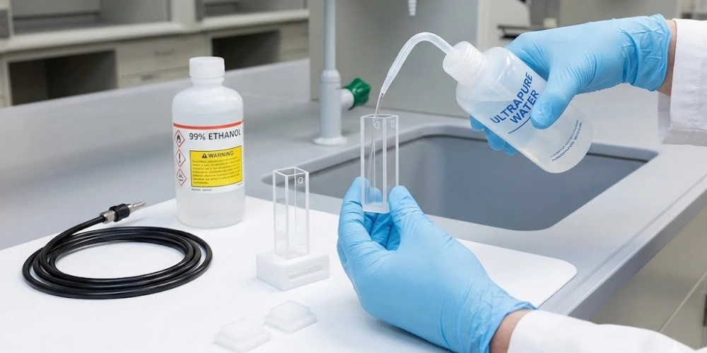
Standard Cleaning Protocol for Quartz Fluorescence Cuvettes
With contamination types and their binding mechanisms established, the cleaning sequence can be structured as a rational, stepwise protocol rather than an ad hoc rinsing routine. Cleaning a quartz fluorescence cuvette effectively requires matching the chemical nature of each residue to an appropriate solvent system, applying mechanical action through fluid dynamics rather than abrasion, and verifying cleanliness at each stage. The following protocol reflects established practice in spectroscopic laboratories and accounts for the mechanical fragility of polished fused silica optical surfaces.
Immediate Rinsing After Sample Removal
The interval between sample removal and the first rinse is one of the most consequential variables in the entire cleaning process. Protein adsorption to silica increases dramatically with contact time: adsorbed protein mass approximately doubles between 5 minutes and 30 minutes of contact, and after 60 minutes, many proteins transition from a reversibly adsorbed to an irreversibly denatured state on the surface.
The first rinse should be initiated within two minutes of sample removal whenever possible. For aqueous samples, the initial rinse should use the same aqueous solvent system as the sample — typically ultrapure water or the corresponding buffer without analyte — to avoid precipitation of sparingly soluble components at a solvent interface.
For organic solvent samples, the first rinse should use the same or a miscible organic solvent, not water, since adding water to residual organic solvent can precipitate dissolved organic compounds onto the walls. Filling the cuvette completely and inverting it three to five times before emptying constitutes an adequate first rinse for freshly deposited samples.
Solvent Selection Based on Contamination Type
The choice of cleaning solvent follows a systematic escalation logic: begin with the mildest effective solvent and progress to more aggressive reagents only when milder options prove insufficient.
Solvent Escalation Protocol for Cuvette Cleaning
| Step | Solvent | Target Contamination | Contact Time | Temperature |
|---|---|---|---|---|
| 1 | Ultrapure water (18.2 MΩ·cm) | Aqueous salts, loose residues | 3–5 rinses | Ambient |
| 2 | 99% Ethanol (EtOH) | Organic compounds, sebum, dyes | 3–5 rinses | Ambient |
| 3 | Isopropanol (IPA) | Greasy films, wax esters | 2–3 rinses | Ambient |
| 4 | Acetone | Aromatic compounds, resins | 2–3 rinses | Ambient |
| 5 | 0.1 M HNO₃ (dilute nitric acid) | Fluorescent dye adsorption, metal ions | 10–30 min soak | Ambient |
| 6 | 0.1 M NaOH | Protein films, biological matrix | 10–20 min soak | 30–40 °C |
| 7 | Tergazyme 1% (w/v) | Stubborn protein, enzymatic digestion | 30–60 min soak | 37 °C |
Concentrated acids (>1 M HCl or H₂SO₄) and strong alkalis (>0.5 M NaOH) must be avoided: concentrated sulfuric acid can etch the fused silica surface at elevated temperatures, while high-concentration NaOH attacks the silica matrix through nucleophilic dissolution of Si–O–Si bonds, permanently degrading optical flatness.
Manual Rinsing Technique Without Mechanical Abrasion
The polished optical faces of a fused silica cuvette achieve surface roughness values of less than 1 nm RMS (root mean square)2. Any contact with solid objects — cotton swabs, brush bristles, lens paper, or even soft laboratory wipes — introduces microscopic scratches across this surface. Even a single pass of a cotton swab under mild pressure can create linear scratches 0.5–2 µm wide and 50–200 nm deep, which are permanent, cannot be polished out in the field, and scatter light directly into the emission detection path.
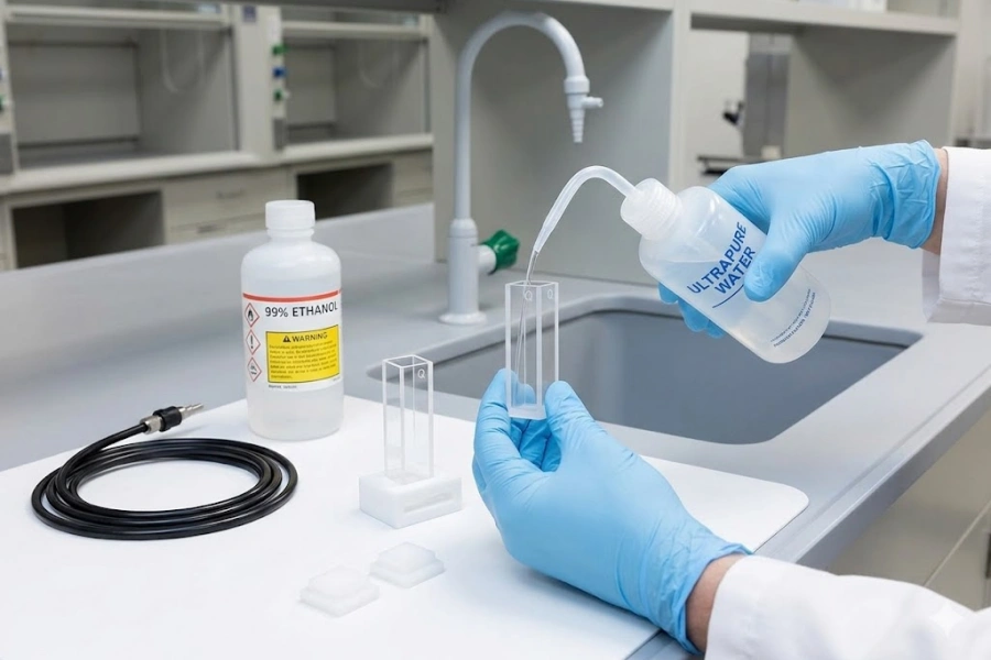
The correct rinsing technique is entirely non-contact. Solvent is introduced using a wash bottle or syringe into the cuvette interior; the cuvette is then sealed with a gloved fingertip over the opening, inverted, and gently agitated to allow the solvent to contact all interior walls. This fill-invert-agitate cycle should be repeated a minimum of five times per solvent, with fresh solvent used for each cycle rather than reusing the same aliquot.
The cuvette should always be held by the frosted or opaque upper rim and the non-optical side faces, with fingers kept entirely away from the four polished windows. Latex gloves are inappropriate because they can deposit plasticizer residues; powder-free nitrile gloves are the laboratory standard for this work.
Ultrasonic Cleaning Conditions and Limitations
Ultrasonic cleaning uses high-frequency acoustic cavitation to dislodge adhered residues without mechanical contact, making it a valuable tool for stubborn deposits that resist solvent rinsing alone. The recommended ultrasonic frequency for fused silica cuvettes is 35–45 kHz, as lower frequencies (20–25 kHz) generate larger, more energetic cavitation bubbles that can induce microfractures at pre-existing surface defects.
The cuvette should be placed upright in a dedicated cuvette rack within the ultrasonic bath, fully submerged in the cleaning solvent (typically dilute ethanol or ultrapure water). Maximum recommended sonication time is 10–15 minutes per cycle at temperatures not exceeding 40 °C; prolonged sonication at elevated temperatures can stress the optical cement in bonded cuvette designs, though solid fused silica cells are more tolerant.
After sonication, a minimum of three complete fill-invert-agitate rinse cycles with ultrapure water are required to remove both the displaced contaminants and any residual cleaning solution from the cuvette interior. Skipping the post-sonication rinse leaves the displaced contaminants suspended in the cleaning solvent, from which they may redeposit as the cuvette dries.
Final Rinse with Ultrapure Water and Verification
The final rinse step is not a formality — it is a critical quality control stage. Ultrapure water with a resistivity of 18.2 MΩ·cm (Type 1 reagent water per ASTM D1193) is the mandatory standard for the final rinse of cuvettes used in fluorescence spectroscopy. Water of lower purity contains dissolved organic carbon (DOC) at concentrations of 50–500 ppb, which leaves a fluorescent organic film upon drying.
A minimum of three consecutive final rinses with Type 1 ultrapure water should be performed, each using a fresh aliquot and the complete fill-invert-agitate cycle. After the final rinse, cleanliness can be provisionally assessed by examining the draining water: if it runs off the interior walls in a continuous sheet rather than forming discrete droplets, the hydrophilic silica surface is free of hydrophobic contamination.
For quantitative verification, a blank fluorescence spectrum of the rinsed cuvette filled with ultrapure water should produce a flat baseline with emission intensity below 5 RFU across the 300–600 nm range when measured against an air reference. Values above this threshold indicate residual fluorescent contamination requiring additional cleaning cycles.
Standard Cleaning Protocol Sequence Summary
| Stage | Action | Solvent / Method | Cycles / Duration | Acceptance Criterion |
|---|---|---|---|---|
| 1. Immediate rinse | Fill-invert-agitate | Same as sample solvent | 3–5× | Visible sample removed |
| 2. Solvent wash | Fill-invert-agitate | EtOH or solvent per table | 5× | No visible residue |
| 3. Ultrasonic (if needed) | Submerged sonication | Dilute EtOH or water | 10–15 min, ≤40 °C | Residue dislodged |
| 4. Post-sonic rinse | Fill-invert-agitate | Ultrapure water | 3× | Sonic residues removed |
| 5. Final rinse | Fill-invert-agitate | Type 1 ultrapure water | 3× | Sheet drainage pattern |
| 6. Blank verification | Fluorescence scan | Ultrapure water in cuvette | 1 scan | <5 RFU at 300–600 nm |
Targeted Removal of Stubborn Residues on Quartz Cuvette Surfaces
Standard solvent rinsing effectively addresses freshly deposited and moderately adhered residues, but certain contamination scenarios — prolonged protein contact, high-affinity fluorescent dye adsorption, or crystallized inorganic matrix — require specialized chemical intervention. The protocols in this section should be applied only after the standard cleaning sequence has been exhausted, as they involve more reactive reagents that demand careful handling and thorough neutralization. Matching the chemical approach to the specific residue class remains the guiding principle.
Dissolving Protein Films with Alkaline or Enzymatic Solutions
Protein films on fused silica can be disrupted by alkaline hydrolysis using 0.1–0.5 M NaOH solution. At pH values above 11, the peptide bonds of adsorbed proteins undergo slow hydrolysis, releasing smaller peptide fragments with reduced surface affinity that can be rinsed away with aqueous solvent. The fused silica surface is stable in dilute alkali for short contact periods: exposure to 0.1 M NaOH for up to 30 minutes at room temperature produces negligible surface etching, as measured by atomic force microscopy (AFM)3 surface roughness analysis in published studies.
The NaOH solution is introduced into the cuvette using a pipette, the cuvette is sealed and allowed to stand for 15–30 minutes, then emptied and immediately rinsed with copious ultrapure water. A minimum of seven ultrapure water rinse cycles following NaOH treatment is essential to return the internal pH to neutrality, as residual alkali will itself fluoresce weakly in the UV range and will interfere with subsequent protein fluorescence measurements.
For cases where NaOH treatment fails — typically with heavily denatured, cross-linked protein matrices — enzymatic digestion using Tergazyme (protease-containing alkaline cleaner) at 1% (w/v) in 40 °C water for 45–60 minutes provides effective proteolytic degradation of residual protein films without chemical attack on the silica surface.
Removing Fluorescent Dye Adsorption with Acid Wash Procedures
Fluorescent dyes adsorbed onto fused silica through ionic interactions with surface silanol groups are disrupted most effectively by acid washing with dilute mineral acid, typically 0.1–1.0 M HNO₃ (nitric acid). The protonation of surface silanol groups under acidic conditions reduces their charge density and weakens the electrostatic interaction with anionic dye molecules such as fluorescein dianion and sulfonated rhodamine derivatives.
A 0.1 M HNO₃ soak for 20–30 minutes at room temperature is sufficient for most standard fluorescent dye residues, including rhodamine B, fluorescein isothiocyanate (FITC), and BODIPY-based labels. For strongly adsorbed cationic dyes such as crystal violet or acridine orange, which interact through cation exchange with negatively charged silanol sites, the HNO₃ concentration can be raised to 1.0 M, but contact time should be limited to 15 minutes at this concentration.
Following acid wash, a minimum of five complete rinse cycles with ultrapure water are required, and the pH of the final rinse effluent should be verified with pH indicator paper to confirm return to neutrality (pH 6.5–7.5) before the cuvette is used for measurement.
Eliminating Salt Crystallization with Chelating Rinses
Crystallized inorganic salt deposits — particularly phosphate, carbonate, and divalent metal-containing buffers — respond poorly to pure water rinsing at room temperature because the dissolution rate of the crystal lattice is kinetically limited. A 5–10 mM EDTA (ethylenediaminetetraacetic acid) solution at pH 7.5 is effective for chelating calcium and magnesium ions from crystallized biological buffers, disrupting the ionic lattice and promoting dissolution.
For phosphate salt crystallization specifically, warm ultrapure water at 50–60 °C dramatically accelerates dissolution due to the increased solubility of phosphate salts at elevated temperatures. The cuvette should be filled with warm ultrapure water and allowed to equilibrate for 5–10 minutes before the standard rinse cycle is performed.
EDTA solutions used for chelating rinses should not exceed 20 mM concentration and must be thoroughly rinsed away with Type 1 ultrapure water afterward, as residual EDTA exhibits weak UV absorption near 220 nm and can interfere with measurements in the deep-UV region.
Specialized Cleaning Reagents and Their Conditions
| Target Residue | Reagent | Concentration | Contact Time | Temperature | Post-Treatment |
|---|---|---|---|---|---|
| Protein film | NaOH | 0.1–0.5 M | 15–30 min | Ambient | 7× ultrapure water rinse |
| Cross-linked protein | Tergazyme | 1% (w/v) | 45–60 min | 37–40 °C | 5× ultrapure water rinse |
| Anionic fluorescent dye | HNO₃ | 0.1–1.0 M | 15–30 min | Ambient | 5× ultrapure water + pH check |
| Cationic fluorescent dye | HNO₃ | 1.0 M | ≤15 min | Ambient | 5× ultrapure water + pH check |
| Phosphate / carbonate salt | Hot ultrapure water | N/A | 5–10 min | 50–60 °C | 3× ultrapure water rinse |
| Ca²⁺ / Mg²⁺ buffer salt | EDTA solution | 5–10 mM, pH 7.5 | 15–20 min | Ambient | 5× ultrapure water rinse |
Drying and Storage of Clean Quartz Fluorescence Cuvettes
Achieving a chemically clean interior surface after washing is only half of the process; how the cuvette is dried and subsequently stored determines whether that cleanliness is preserved until the next use. A cuvette that has been cleaned to a blank fluorescence of less than 2 RFU can be rendered unusable by improper drying that leaves a residual water film containing dissolved organic carbon, or by storage conditions that allow airborne particulate contamination to settle onto the optical faces.
Nitrogen Purging as the Preferred Drying Method
Nitrogen gas purging is the gold standard for drying fused silica optical components because filtered dry nitrogen introduces no chemical contamination, removes solvent vapor rapidly, and avoids the thermal stress that oven drying can impose on optically bonded cuvettes.
Compressed nitrogen used for cuvette drying must be filtered through an activated carbon trap and a 0.2 µm particle filter positioned immediately upstream of the dispensing nozzle. Without filtration, compressor oil aerosols and hydrocarbon vapors in the nitrogen supply will deposit directly on the cuvette interior, recontaminating the cleaned surface.
The nitrogen nozzle should be held approximately 1–2 cm from the cuvette opening and directed at a slight angle to the interior axis, allowing displaced solvent vapor to exit while fresh dry gas fills the cell. A drying time of 30–60 seconds of continuous nitrogen flow is adequate for a standard 10 mm path length, 3.5 mL cuvette at ambient temperature.
Air Drying in a Controlled Environment
When nitrogen purging is unavailable, inverted air drying on a clean Class 100 laminar flow bench is an acceptable alternative for routine laboratory use, provided the ambient particulate level is controlled. The cuvette should be inverted onto a clean, solvent-rinsed polytetrafluoroethylene (PTFE) drying rack rather than paper or fabric, to prevent fiber transfer to the optical aperture.
Complete air drying of a 10 mm standard cuvette under laminar flow at 22 °C typically requires 20–40 minutes depending on ambient relative humidity. At relative humidity above 65%, drying time extends significantly and the risk of condensation-assisted recontamination increases. In high-humidity laboratory environments, drying within a low-humidity enclosure containing fresh silica gel desiccant is preferable.
Oven drying at temperatures above 100 °C is contraindicated for cuvettes with optical cement bonds, as differential thermal expansion between the fused silica windows and the cement layer can introduce internal stress that eventually causes delamination. Monolithic fused silica cuvettes without cement bonding are more thermally tolerant but still present unnecessary risk.
Storage Conditions That Prevent Recontamination
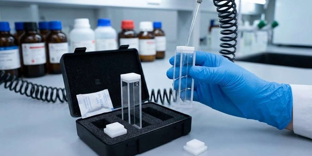
Cleaned cuvettes should be stored in individual compartmentalized cases with form-fitting foam or PTFE inserts that contact only the frosted or opaque surfaces of the cuvette, keeping the optical faces free from contact stress. Loose storage of multiple cuvettes in a common container creates collision risk: a single impact between two fused silica cells traveling less than 2 mm can create a chip or edge fracture that propagates across the optical face under subsequent thermal cycling.
A silica gel or molecular sieve desiccant pack should be included in the storage case to maintain relative humidity below 30%, suppressing the thin-film adsorption of atmospheric water vapor and dissolved VOCs onto the silica surface. Cases should be stored in a drawer or cabinet away from direct UV exposure, as ambient UV from building lighting systems can induce slow photochemical reactions in trace organic residues remaining on the surface, generating new fluorescent photoproducts.
For cuvettes that will not be used for an extended period — more than two weeks — a final rinse with freshly prepared 99% ethanol followed by nitrogen purging and sealed storage provides additional protection against microbial growth and VOC adsorption.
Drying and Storage Conditions Reference
| Parameter | Nitrogen Purge | Laminar Flow Air Dry | Storage Case |
|---|---|---|---|
| Time to complete dryness | 30–60 seconds | 20–40 minutes | N/A |
| Contamination risk | Very Low (with filtration) | Low (in Class 100 environment) | Very Low (desiccated, sealed) |
| Humidity requirement | N/A | <65% RH | <30% RH |
| Temperature range | Ambient | Ambient | Ambient (avoid >40 °C) |
| Suitability for bonded cuvettes | Yes | Yes | Yes |
| Suitability for monolithic cuvettes | Yes | Yes | Yes |
Physical Damage Versus Chemical Contamination in Quartz Cuvettes
Before committing to an intensive cleaning cycle, distinguishing between residue that can be removed and damage that is permanent is a necessary diagnostic step that saves both time and reagents. Chemical contamination — regardless of its tenacity — responds in principle to the appropriate solvent or reagent. Physical damage to the fused silica surface, by contrast, is irreversible under laboratory conditions and cleaning cannot restore optical performance.
-
Raking light inspection is the most accessible diagnostic method. Holding the cuvette at a 15–20 degree angle to a focused white LED torch or penlight in a darkened room reveals surface topography by casting shadows across any raised or recessed features. Contamination films typically appear as iridescent, color-shifting interference patterns or as diffuse haziness that changes appearance as the angle of illumination is varied. True scratches appear as sharp, fixed linear features with consistent orientation that do not shift color or disappear at any angle of illumination. Pits and chips create defined shadow edges at their margins.
-
Chemical contamination responds to solvent, even if not to the first solvent applied. Applying a drop of 99% ethanol to a suspicious surface feature and observing whether the feature changes, diminishes, or disappears upon evaporation is a useful field test: a contamination film will typically show visible disruption or thinning, while a physical scratch remains entirely unchanged. A blank fluorescence scan before and after a single ethanol rinse that shows a measurable reduction in background signal confirms the contamination hypothesis, whereas no change in the scan after cleaning confirms permanent surface damage.
-
Subsurface damage — internal stress fractures or delamination in bonded cells — manifests as fixed internal features visible under strong transmitted illumination. These features scatter light into the emission optical path in a manner that cannot be resolved by surface cleaning. Distinguishing subsurface fractures from surface contamination requires examining the cuvette under transmitted light from a collimated source: contamination is always located precisely on the interior wall plane, whereas subsurface fractures appear at varying depths depending on the focal plane of the observation.
A scratched or structurally compromised quartz fluorescence cuvette should be retired from fluorescence measurements, as continued use generates unreproducible background scatter that cannot be corrected algorithmically.
Verifying Cuvette Cleanliness Before Fluorescence Measurements
Even after meticulous cleaning, confirming that the cuvette meets the required background specification before loading the experimental sample eliminates the risk of attributing residual contamination to the sample or instrument.
-
Blank fluorescence scanning is the definitive verification method. The cleaned cuvette is filled with the same solvent to be used in the experiment — typically the buffer blank or pure solvent — and a full emission scan is acquired over the anticipated measurement range. A background intensity below 5 RFU across the 300–600 nm range with an excitation wavelength appropriate to the experiment (commonly 280–350 nm) is the acceptance threshold for most quantitative fluorescence applications. A background above this threshold requires an additional cleaning cycle before the experiment proceeds.
-
UV-Vis transmission baseline verification provides a complementary check, particularly sensitive to UV-absorbing inorganic and organic residues. Filling the cuvette with Type 1 ultrapure water and recording the UV-Vis absorbance spectrum against a reference cuvette (or air blank) should yield an absorbance value below 0.005 AU at 260 nm and below 0.002 AU at 340 nm. Elevated absorbance at specific wavelengths provides information about the chemical class of the residue: absorption at 260–280 nm indicates nucleic acid or aromatic protein fragments; absorption at 220–240 nm suggests inorganic salt or nitric acid carryover from acid washing.
-
Visual inspection under oblique illumination, as described in the physical damage section, serves as a rapid pre-screening step that can identify heavy contamination before instrument time is consumed in blank scanning. A cuvette that passes visual inspection but fails the blank fluorescence test harbors sub-visual contamination — typically a partial monolayer of adsorbed organic material — that requires targeted chemical treatment rather than additional rinsing.
Systematic verification before each experimental use, while adding two to five minutes to the preparation workflow, eliminates the far greater time cost of repeating experiments compromised by undetected cuvette contamination.
Handling Practices That Minimize Contamination Risk
Reducing the frequency and severity of contamination before it occurs is more efficient than removing it after the fact. Consistent adherence to correct handling practices at every stage of cuvette use — sample loading, removal, and interim storage — substantially reduces the cleaning burden and prolongs service life.
-
Glove selection and hand position are the first line of defense. Powder-free nitrile gloves with a thickness of 0.1–0.15 mm provide adequate protection against sebum transfer without compromising tactile sensitivity for handling small optical components. The cuvette should be gripped exclusively by the frosted upper rim or the opaque side faces, maintaining a minimum 5 mm clearance from all four polished optical windows at all times. Even brief contact of a gloved fingertip with a polished window deposits nitrile polymer fragments detectable by fluorescence spectroscopy at 350 nm excitation.
-
Sample filtration before loading is a practice that simultaneously protects cuvette cleanliness and improves data quality. Passing samples through a 0.2 µm syringe filter removes particulates that would otherwise scatter into the emission detector and deposit on the interior walls as the solvent evaporates between measurements. Biological samples with high protein concentrations (>1 mg/mL) benefit additionally from centrifugation at 10,000 × g for five minutes to remove aggregated protein particles before filtration. The reduction in particulate loading not only produces smoother emission spectra but measurably reduces the degree of protein film formation on the cuvette walls within a single measurement session.
-
Pipette insertion depth and tip selection affect contamination distribution within the cuvette interior. A standard 1 mL pipette tip inserted to the bottom of a 10 mm path length cuvette will contact the inside of the base, potentially scratching the fused silica floor or depositing pipette tip material. The tip should be lowered to the midpoint of the cuvette body to dispense sample with minimum wall contact, allowing capillary flow to distribute the liquid. Polypropylene pipette tips are preferred over those containing plasticizers, as plasticizer migration into the sample during extended contact can introduce UV-absorbing and fluorescent contamination.
Maintaining a clean laboratory bench surface beneath the cuvette workstation and using dedicated optical work mats — rinsed weekly with ethanol and allowed to fully dry — completes the environmental contamination control framework.
Service Life Assessment for Quartz Fluorescence Cuvettes
No cleaning protocol, however rigorous, can restore a cuvette whose optical surfaces have degraded beyond functional tolerance. Recognizing when a quartz fluorescence cuvette has reached the end of its serviceable life is as important as knowing how to clean it, because continued use of a degraded cuvette generates systematically erroneous data that may not be immediately identifiable as instrument or cuvette error.
The primary retirement criterion is UV transmission loss exceeding 15% at 250 nm relative to the manufacturer's specification or a reference measurement taken when the cuvette was new. A transmission below 85% at 250 nm, even after complete cleaning, indicates either surface etching — commonly from repeated exposure to concentrated alkali or acid — or accumulated sub-surface damage from micro-fracturing. This threshold is conservative but appropriate for quantitative fluorescence work; for qualitative screening purposes, slightly degraded cuvettes may remain serviceable if the transmission loss is uniform across both excitation and emission windows.
Persistent fluorescence background above 10 RFU in the 300–500 nm range that does not respond to the complete cleaning protocol including acid wash and enzymatic treatment indicates irreversibly adsorbed fluorescent material, likely photoproducts from prolonged laser irradiation or covalently modified silica surface groups formed during reactive sample exposure. Once this baseline contamination is irreducible, the cuvette introduces a fixed error that cannot be corrected by subtraction because its magnitude varies with temperature, humidity, and cuvette positioning in the instrument.
Optical path length deviation is a further retirement criterion. New precision fused silica cuvettes are fabricated with path length tolerances of ±0.01 mm for 10 mm cells (per ISO 9001 optics standards). Repeated thermal cycling, mechanical impact, or delamination in bonded designs can cause dimensional drift outside this tolerance. While path length deviation is not detectable by fluorescence measurement alone, absorbance at a standard chromophore (such as 1 mM K₂Cr₂O₇ in dilute H₂SO₄ at 373 nm, ε = 4820 M⁻¹cm⁻¹) compared against a certified reference value provides a direct check on geometric integrity.
Retirement Decision Reference for Quartz Cuvettes
| Performance Parameter | Acceptable Range | Marginal | Retire Immediately |
|---|---|---|---|
| UV transmission at 250 nm | >90% | 85–90% | <85% |
| Blank fluorescence (300–600 nm) | <5 RFU | 5–15 RFU | >15 RFU (irreducible) |
| Path length deviation (10 mm cell) | ±0.01 mm | ±0.02–0.05 mm | >±0.05 mm |
| Surface scratch depth (visual) | None visible | Hairline, outside beam path | Any scratch in beam path |
| Post-clean UV absorbance at 260 nm | <0.005 AU | 0.005–0.02 AU | >0.02 AU (persistent) |
Conclusion
Maintaining a quartz fluorescence cuvette in optimal condition requires an integrated approach that spans contamination identification, appropriate solvent selection, non-abrasive cleaning mechanics, controlled drying, and systematic verification. Each step in the sequence described here addresses a specific failure mode — whether chemical, mechanical, or procedural — and omitting any stage risks reintroducing the contamination it was designed to prevent. The cleaning protocols presented are grounded in the physicochemical properties of fused silica surfaces and the binding behaviors of the most common laboratory residue classes. Applied consistently, these practices extend cuvette service life, reduce measurement uncertainty, and protect the integrity of fluorescence spectroscopic data across all concentrations and wavelength ranges.
FAQ
Can a quartz fluorescence cuvette be cleaned with soap or detergent?
Mild laboratory-grade detergents such as 1% Hellmanex III or 0.1% Triton X-100 can be used for routine cleaning of heavily soiled cuvettes, provided they are followed by an extensive ultrapure water rinse sequence of at least seven complete cycles. Consumer dish soaps must never be used, as they contain optical brighteners — fluorescent whitening agents — that adsorb tenaciously to fused silica and produce strong, broad emission bands across 400–500 nm that are virtually impossible to remove completely.
How often should a blank fluorescence scan be run to verify cuvette cleanliness?
A blank verification scan should be performed before every experimental session and after any cleaning cycle that followed a particularly contaminating sample type — including concentrated proteins, high-affinity fluorescent dyes, or photochemically reactive compounds. In routine laboratory practice where the same cuvette is used multiple times per day with similar aqueous samples, a single morning verification followed by immediate rinsing after each measurement provides adequate quality control.
Is it safe to use a quartz fluorescence cuvette with hydrofluoric acid samples?
Hydrofluoric acid (HF) in any concentration is incompatible with fused silica cuvettes. HF reacts with silicon dioxide to form silicon tetrafluoride and hexafluorosilicic acid, etching the optical surface at rates that are measurable even at HF concentrations below 1 mM. A single exposure to HF permanently degrades the surface flatness and UV transmission of a fused silica cuvette, rendering it unfit for further precision spectroscopic use.
What is the difference between a standard quartz cuvette and a fluorescence-grade quartz cuvette?
Standard spectrophotometric quartz cuvettes are fabricated with two polished optical windows for transmission measurements. A fluorescence-grade quartz fluorescence cuvette features four polished optical windows — all four vertical faces are optically finished to the same flatness and parallelism specification — allowing the 90-degree excitation/emission geometry of fluorescence spectrometers to function correctly. Using a two-window cuvette in a fluorescence spectrometer places an unpolished, optically rough face at the emission collection angle, generating high levels of scatter and completely compromising measurement accuracy.
References:
-
The Vroman effect describes the competitive and sequential displacement of proteins adsorbed onto solid surfaces, a process that determines the final composition of protein films on optical materials. ↩
-
Root mean square (RMS) surface roughness is the standard metrological parameter used to quantify the flatness and polish quality of optical surfaces, including fused silica cuvette windows. ↩
-
Atomic force microscopy (AFM) is a high-resolution scanning probe technique capable of imaging surface topography at the nanometer scale, used to characterize scratch depth and surface roughness on optical components. ↩