Engineers specifying quartz tube materials frequently encounter performance failures traceable to a single misunderstood distinction. Choosing the wrong variant between opaque and transparent quartz costs thermal efficiency, process yield, and component service life.
Both tube types originate from the same high-purity fused silicon dioxide feedstock, yet their microstructural differences produce measurably divergent optical, radiative, and functional behaviors across every major industrial application. This article resolves that distinction with full technical precision — covering optical transmission, infrared emission, thermal shock response, UV behavior, chemical purity, dimensional specifications, and an eight-scenario selection matrix — so that every specification decision rests on verified material data rather than assumption.
The performance gap between these two tube variants becomes fully visible only when each physical property is examined in sequence, from the atomic scale of the fused silica network outward to the system-level consequences in production environments. That is the analytical sequence this article follows.
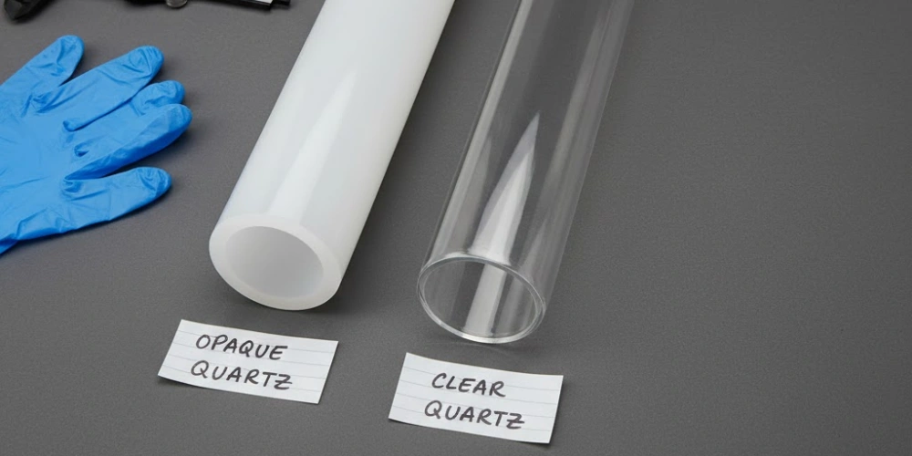
A Shared Material Origin with Divergent Microstructures
Recognizing that both tube variants share an identical chemical foundation is the essential first step before any performance comparison can be interpreted correctly.
-
Common base material: Both transparent and opaque quartz tubes are manufactured from high-purity fused silicon dioxide (SiO₂), with purity levels at or above 99.9% SiO₂ in standard industrial grades and reaching 99.999% in semiconductor-qualified material. The elemental composition of the two tube types is, within measurement resolution, chemically indistinguishable when produced from the same feedstock batch.
-
Transparent tube fabrication: Transparent quartz tubes are produced through a bubble-free fusion process — either electric arc fusion or flame hydrolysis1 — in which the silica melt is held at temperatures exceeding 2,000°C under controlled conditions that suppress nucleation of gas inclusions. The resulting material is an optically homogeneous amorphous glass with no internal scattering centers, transmitting electromagnetic radiation across a broad spectral window from deep UV through near-infrared.
-
Opaque tube fabrication: The milky-white opacity of opaque quartz tubes arises from the deliberate introduction of microscopic gas-filled voids — typically air or CO₂ — into the silica melt during the flame-fusion stage. These voids, ranging in diameter from approximately 1 µm to 100 µm, are distributed uniformly throughout the tube wall and sealed permanently within the glass network upon solidification. Their diameter range relative to the wavelengths of visible light (400 nm to 700 nm) satisfies the geometric optics scattering condition, producing near-total scattering of incident visible and UV photons and generating the characteristic opaque appearance.
The critical implication for material engineers is that substituting one tube type for the other is not a question of purity downgrade or material compromise — it is a question of selecting the correct microstructural architecture for the radiative and optical demands of the specific process environment. All performance differences documented in the following sections originate exclusively from this microstructural divergence, not from any difference in base chemical composition.
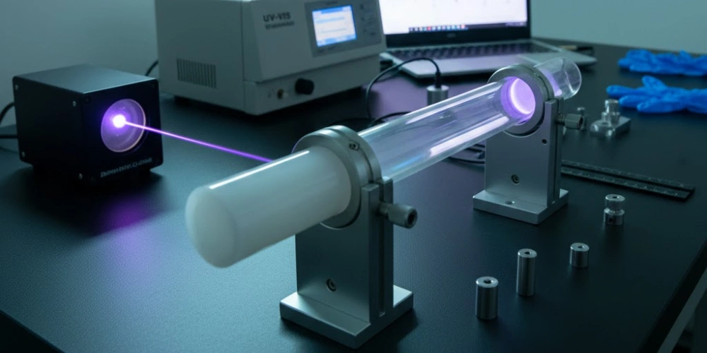
Optical Transmission Profiles of Both Tube Variants
Quantifying the spectral transmission behavior of each tube type across the full electromagnetic range used in industrial processing establishes the physical foundation for every application-specific comparison that follows.
-
Transparent quartz UV transmission: High-purity transparent quartz tubes transmit 70% to 90% of incident radiation in the UV-C band (200 nm to 280 nm), 80% to 90% in UV-B (280 nm to 315 nm), and 85% to 92% in UV-A (315 nm to 400 nm). The short-wavelength transmission cutoff is strongly influenced by OH content: low-OH transparent quartz (< 30 ppm OH) maintains transmission down to approximately 165 nm, while high-OH grades (> 150 ppm OH) exhibit a red-shifted cutoff near 200 nm to 220 nm due to OH-related absorption bands in the VUV range.
-
Transparent quartz visible and NIR transmission: In the visible range (400 nm to 700 nm), transmission exceeds 90% for standard wall thicknesses of 2 mm to 3 mm. In the near-infrared (700 nm to 2,500 nm), transmission remains between 60% and 85%, declining gradually with increasing wall thickness and OH content due to overtone absorption of SiO-H stretching vibrations near 1,380 nm and 2,210 nm.
-
Opaque quartz transmission across all bands: Opaque quartz tubes exhibit transmission below 5% across the entire UV, visible, and NIR spectral range (100 nm to 2,500 nm). This near-total opacity results from the combined effect of scattering by internal voids (dominant mechanism for visible light) and absorption by the SiO₂ matrix (dominant mechanism in UV-C). In the mid-infrared range (2.5 µm to 25 µm), both tube types transition from transmission-dominant to emission-dominant behavior; however, the emissivity of opaque tubes in this range (ε ≈ 0.90 to 0.95) substantially exceeds that of transparent tubes (ε ≈ 0.60 to 0.75), a difference with direct consequences for infrared heating efficiency examined in the next section.
Spectral Transmission and Emission Properties
| Spectral Band | Wavelength Range | Transparent Quartz Transmission | Opaque Quartz Transmission |
|---|---|---|---|
| UV-C | 200–280 nm | 70–90% | < 5% |
| UV-B | 280–315 nm | 80–90% | < 5% |
| UV-A | 315–400 nm | 85–92% | < 5% |
| Visible | 400–700 nm | > 90% | < 5% |
| NIR | 700–2,500 nm | 60–85% | < 5% |
| SWIR | 1.0–2.5 µm | 55–80% | < 5% |
| MWIR emissivity (ε) | 2.5–25 µm | 0.60–0.75 | 0.90–0.95 |
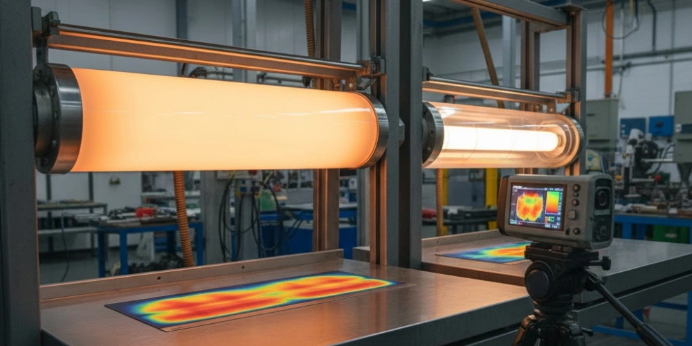
Infrared Radiative Performance in Opaque versus Transparent Quartz Tubes
Among all performance dimensions separating these two tube materials, infrared radiative behavior carries the greatest practical consequence for industrial heating applications, where energy delivery efficiency and spatial uniformity directly affect product quality and operating economics. The internal void structure of opaque quartz tubes fundamentally alters the interaction between the tube wall and thermal radiation in ways that transparent quartz cannot replicate. Accordingly, the three subsections below address emissivity, spatial uniformity, and energy conversion efficiency as distinct but interconnected aspects of the same radiative physics.
Emissivity Values and Blackbody Approximation Across Temperature Ranges
The emissivity of a radiating surface quantifies its thermal emission output relative to a perfect blackbody at the same temperature, making it the single most important parameter for comparing the infrared heating performance of the two tube types.
An opaque quartz tube operating at 900°C (1,173 K) emits thermal radiation at a power density of approximately ε × σ × T⁴ = 0.92 × 5.67 × 10⁻⁸ × (1,173)⁴ ≈ 101 kW/m² from its outer surface. A transparent quartz tube at the same temperature, with ε ≈ 0.68 in the MWIR band, emits approximately 75 kW/m² — a 26% deficit in radiated power per unit surface area under identical operating conditions.
This emissivity gap narrows at lower operating temperatures but remains significant across the full industrial service range. At 700°C (973 K), the emitted power difference between ε = 0.92 and ε = 0.68 corresponds to approximately 18 kW/m²; at 1,100°C (1,373 K), the gap widens to approximately 39 kW/m². The physical origin of the higher emissivity in opaque tubes lies in the internal void structure: each void-matrix interface acts as an additional phonon scattering and photon absorption site, increasing the effective optical path length within the tube wall and bringing the material's radiative behavior closer to the blackbody limit.
Transparent quartz tubes, in contrast, allow a fraction of thermal radiation to transmit directly through the tube wall without being re-emitted from the surface — an effect that becomes measurable above 700 nm where silica's intrinsic absorption coefficient falls. This partial transmission means that a portion of the radiative energy budget bypasses the tube surface entirely, reducing the effective emissivity relative to the true surface temperature.
Spatial Irradiance Uniformity at the Heated Product Surface
Beyond total radiated power, the spatial distribution of irradiance at the product surface is the parameter that most directly affects heating uniformity and product quality in continuous manufacturing operations.
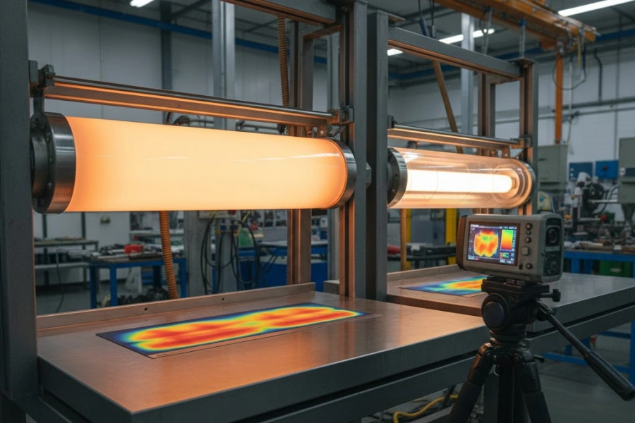
Transparent quartz tubes transmit a significant fraction of NIR radiation originating from internal heating elements — tungsten coil filaments or silicon carbide resistors — directly through the tube wall without attenuation. Because resistive heating elements are wound in a helical pitch, the NIR flux transmitted through the tube wall exhibits periodic intensity modulation at a spatial frequency corresponding to the element pitch, typically 15 mm to 40 mm. At the product surface, this modulation produces irradiance non-uniformity with peak-to-average ratios of 1.4 to 2.1, corresponding to temperature variations of ±15°C to ±35°C at typical heating distances of 50 mm to 100 mm from the tube surface.
Opaque quartz tubes eliminate this modulation effect entirely. The scattering void network within the tube wall converts directional NIR flux from the internal element into a diffuse isotropic emission pattern at the outer surface, producing a spatially uniform cylindrical radiating source independent of element pitch geometry. Measured peak-to-average irradiance ratios for opaque tube heaters in comparable configurations are 1.05 to 1.12 — a reduction in non-uniformity of approximately 75% to 85% relative to transparent tube equivalents.
In production environments processing thermally sensitive materials — automotive primer coatings, pharmaceutical blister packaging, thin-film polymer laminates — this uniformity advantage translates to measurable yield improvements. Trials in automotive paint curing lines replacing transparent with opaque quartz tube heater arrays documented reductions in orange-peel surface defect rates from 3.2% to 0.6% of production area, attributed directly to the elimination of periodic irradiance hot spots.
Energy Conversion Efficiency Differentials in Heating Applications
The fraction of electrical input energy that reaches the product surface as useful infrared irradiance differs systematically between the two tube types, with consequences for both operating efficiency and equipment thermal management.
Transparent quartz tubes transmit approximately 15% to 25% of the NIR radiation generated by an internal tungsten element directly through the tube wall and beyond the intended heating zone. In a typical enclosed heating module with a reflective rear wall, a portion of this transmitted radiation is recovered by the reflector and redirected toward the product — but recovery efficiency is limited by reflector geometry and surface reflectance degradation over time. Net transmitted radiation that is not recovered is absorbed by the equipment housing, contributing to housing thermal load and reducing the fraction of input power delivered to the product as useful irradiance.
Opaque quartz tubes retain virtually all generated radiation within the tube wall, absorbing NIR and re-emitting it as diffuse MWIR from the outer surface at the elevated emissivity of ε ≈ 0.90 to 0.95. This absorption-and-re-emission cycle shifts the emission spectrum toward longer wavelengths better matched to the absorption characteristics of common industrial materials — water (peak absorption at 1.94 µm and 2.73 µm), organic polymer coatings (absorption bands at 3.0 µm to 3.5 µm), and carbon-based films. The net result, measured in comparative production trials, is an energy savings of 12% to 18% when opaque tube heater arrays replace transparent tube equivalents in equivalent heating zone configurations.
The equipment-level implication of this efficiency difference is a reduction in housing thermal load that allows smaller cooling systems, reduced insulation thickness, and lower ambient temperatures within the heating module enclosure — all of which extend the service life of ancillary components including reflectors, electrical connections, and ceramic terminal blocks.
Infrared Radiative Performance Summary
| Parameter | Opaque Quartz Tube | Transparent Quartz Tube |
|---|---|---|
| MWIR emissivity (ε) | 0.90–0.95 | 0.60–0.75 |
| Radiated power at 900°C (kW/m²) | ~101 | ~75 |
| Radiated power at 700°C (kW/m²) | ~61 | ~45 |
| Radiated power at 1,100°C (kW/m²) | ~160 | ~118 |
| Peak-to-average irradiance ratio | 1.05–1.12 | 1.4–2.1 |
| NIR wall transmission loss | < 5% | 15–25% |
| Energy efficiency gain (opaque vs. transparent) | +12% to +18% | baseline |
| Dominant emission wavelength at 900°C | ~2.0 µm | ~2.0 µm (partial transmission) |
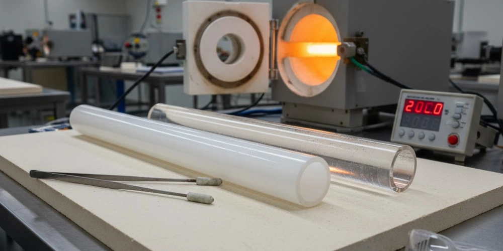
Thermal Shock Resistance and Mechanical Behavior Compared
Mechanical reliability under rapid thermal cycling is a selection criterion that often receives less analytical attention than optical or chemical properties, yet it directly governs tube service life and replacement frequency in furnace loading, infrared heater activation, and sterilization system operation. Both tube variants share the same base fused silica network, but the internal void architecture of opaque tubes introduces a structural variable that requires careful evaluation before assuming mechanical equivalence. The following subsections address thermal expansion, fracture behavior, and dimensional load capacity as separate but related mechanical performance dimensions.
Thermal Expansion Coefficients and Dimensional Stability
The coefficient of thermal expansion (CTE) of fused silica is one of the lowest of any engineered material, and this property is largely preserved in both tube variants regardless of void content.
The CTE of fused silica is approximately 0.55 × 10⁻⁶/°C across the temperature range of 20°C to 1,000°C, independent of whether the material is optically transparent or opaque. Direct dilatometry measurements on opaque fused silica samples with void volume fractions of 5% to 15% — the range typical of commercial opaque quartz tubes — show CTE deviations from the transparent fused silica baseline of less than 3%, which falls within the measurement uncertainty of standard dilatometry instruments. The void phase (air or CO₂) contributes negligibly to macroscopic thermal expansion because the voids are mechanically unconstrained within the surrounding glass matrix.
Dimensional stability in precision-fit applications — particularly in semiconductor diffusion furnace flanges and reactor tube sealing surfaces — is therefore equivalent between the two tube types to within manufacturing tolerance. A tube of either type with an outer diameter of 200 mm at room temperature expands by approximately 0.11 mm when heated to 1,000°C, a predictable and reproducible value that simplifies thermal design of tube-to-flange interfaces. For comparison, alumina ceramic tubes (CTE ≈ 7.4 × 10⁻⁶/°C) expand approximately 13 times more over the same temperature excursion, requiring substantially larger thermal clearance allowances.
The practical consequence of this CTE equivalence is that opaque and transparent quartz tubes can be used interchangeably in applications where only thermal expansion governs fit tolerance — a finding that simplifies retrofit decisions when switching tube types in existing equipment.
Fracture Behavior and Void Structure Effects Under Rapid Thermal Cycling
The presence of internal voids introduces a theoretical fracture mechanics concern — that voids act as stress concentration sites that accelerate crack initiation under thermal stress — which field experience and controlled testing consistently refute.
According to Griffith crack theory2, the critical stress intensity factor for fracture in a brittle material scales with the square root of the largest defect dimension present. For opaque quartz tubes with maximum void diameters of 100 µm, the theoretical critical fracture stress in pure tension is approximately 15 MPa to 25 MPa — well above the thermal stresses generated during standard furnace loading and unloading sequences, which produce peak tensile stresses of 2 MPa to 6 MPa at ramp rates of 5°C/min to 20°C/min. Controlled thermal shock tests — subjecting both tube types to immersion from 1,000°C into a 25°C water bath — show fracture rates of 8% to 12% for both transparent and opaque fused silica tubes of equivalent wall thickness, confirming that the void structure does not statistically increase susceptibility to catastrophic thermal fracture.
Long-cycle thermal fatigue behavior shows a more nuanced picture. In semiconductor diffusion furnace service, both tube types exhibit gradual surface devitrification after repeated thermal cycling above 1,000°C, with devitrification onset appearing as surface cloudiness after approximately 50 to 80 cycles in standard-OH material and after 200 to 400 cycles in low-OH grades. Transparent tubes in optical inspection applications show earlier functional degradation from devitrification — because even minor surface crystallization disrupts UV transmission — while opaque tubes tolerate equivalent surface devitrification without any change in their primary performance characteristic (infrared emission), effectively providing a longer functional service life in heating applications despite identical structural aging rates.
Practically, opaque quartz tubes installed in infrared heating panels operating at 900°C to 1,050°C with daily on/off thermal cycling accumulate 1,000 to 3,000 cycles before surface devitrification produces measurable emissivity reduction — a service duration of 3 to 8 years in continuous production environments operating on single-shift schedules.
Wall Thickness Specifications and Structural Load Capacity
Wall thickness selection governs both mechanical robustness and the thermal mass characteristics that affect heating response time, and the two tube types follow similar but not identical specification conventions.
Standard wall thicknesses for both transparent and opaque quartz tubes range from 1.5 mm (thin-wall lamp and therapy applications) to 8 mm (large-diameter semiconductor process tubes). The presence of internal voids in opaque tubes reduces bulk density by approximately 1% to 3% relative to fully dense transparent fused silica (density 2.20 g/cm³), producing a correspondingly slight reduction in flexural modulus. For tubes with outer diameters below 100 mm, this density reduction has no measurable effect on structural performance under normal operating loads. For large-diameter opaque tubes (200 mm to 360 mm OD) used in horizontal semiconductor furnace installations, the maximum unsupported span at 1,050°C is approximately 400 mm to 500 mm for wall thicknesses of 5 mm to 8 mm — effectively identical to the specification for transparent tubes of equivalent geometry.
Sag behavior in horizontal tube installations is governed by viscous flow of the amorphous silica network at temperatures above the strain point (~1,050°C for fused silica). Both tube types exhibit equivalent sag rates at equivalent temperatures and span lengths because sag is controlled by the viscosity-temperature relationship of the SiO₂ network, which is unchanged by the presence of internal voids. Intermediate ceramic support saddles are required at span intervals of 400 mm to 500 mm for both tube types operating above 1,000°C in horizontal orientation — a design rule applicable without modification regardless of which tube variant is specified.
Thermal and Mechanical Property Summary
| Property | Opaque Quartz Tube | Transparent Quartz Tube |
|---|---|---|
| CTE (×10⁻⁶/°C), 20–1,000°C | 0.55 | 0.55 |
| Bulk density (g/cm³) | 2.13–2.17 | 2.20 |
| CTE deviation due to void structure | < 3% | baseline |
| Max thermal shock fracture rate (1,000°C → 25°C water quench) | 8–12% | 8–12% |
| Service cycles before devitrification (low-OH grade) | 200–400 | 200–400 |
| Functional service life degradation trigger | Emissivity reduction | UV transmission loss |
| Max unsupported horizontal span at 1,050°C (25 mm OD) | 400–500 mm | 400–500 mm |
| Wall thickness range | 1.5–8 mm | 1.5–8 mm |
| Operating cycle life (heating panels, 900–1,050°C) | 1,000–3,000 cycles | 1,000–3,000 cycles |
UV and Visible Light Behavior in Transparent versus Opaque Quartz Tubes
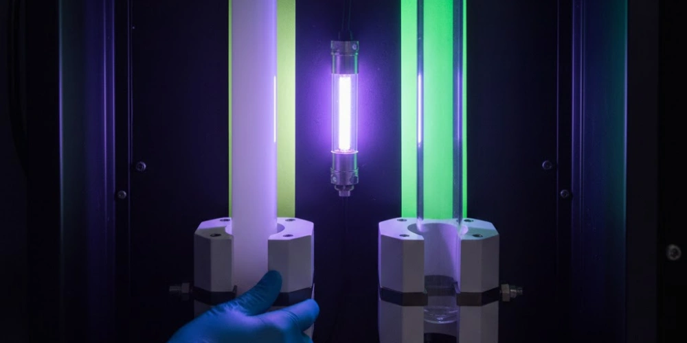
UV performance is the dimension of this comparison most frequently misspecified in practice, with a persistent assumption in some engineering environments that all quartz tubes transmit UV radiation effectively. Transparent quartz tubes do transmit UV across a broad spectral window, but opaque tubes do not — and this distinction is absolute rather than a matter of degree. Moreover, the distinction produces a functional inversion in UV-intensive applications: the tube type that blocks UV becomes the more valuable component, fulfilling optical management and safety functions that the transmitting tube cannot perform. Each of the following subsections examines a distinct facet of this UV behavior divergence.
UV Transmission Windows in Transparent Quartz Across Wavelength Bands
The UV transmission capability of transparent quartz tubes is the defining performance characteristic that makes them irreplaceable in applications requiring photon delivery into or through the tube wall.
High-purity transparent fused silica maintains measurable optical transmission down to approximately 165 nm in low-OH grades (< 30 ppm OH, classified as Type 2 or Suprasil-equivalent), making it one of the few solid optical materials with significant VUV transmission. Standard-grade transparent quartz (OH content 150 ppm to 400 ppm, Type 3 or Infrasil-equivalent) retains full UV-C and UV-A transmission but shows a shifted short-wavelength cutoff near 200 nm to 220 nm due to OH absorption in the 180 nm band. The practical consequence is that lamp grade transparent quartz tubes — specified for UV germicidal lamps at 253.7 nm — can use standard-OH material without spectral penalty, while VUV photochemistry applications below 200 nm require specifically low-OH grades.
Transmission stability under prolonged UV irradiation is a documented concern for transparent quartz tubes in high-intensity UV lamp service. Solarization — the formation of color centers3 (oxygen-deficiency defects, E' centers) under intense UV exposure — reduces UV transmission by 2% to 8% over 500 to 1,000 hours of continuous operation in germicidal lamp applications. Synthetic fused silica (Type 4, OH > 800 ppm) shows the highest solarization resistance due to OH quenching of defect formation, at the cost of reduced short-wavelength cutoff. This solarization behavior is irrelevant to opaque tubes, which contain no meaningful UV transmission to degrade.
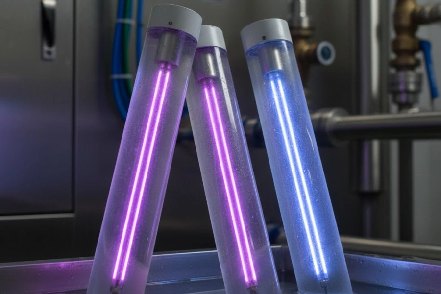
The UV transmission window of transparent quartz makes it the exclusive material choice for UV lamp envelopes (germicidal, deuterium, xenon arc, and excimer lamps), photochemical reactor tubes, UV spectrophotometry flow cells, and solar simulation chambers. No opaque tube variant can serve these functions regardless of purity grade, wall thickness, or fabrication method.
UV Blocking Characteristics and Spectral Filtration by Opaque Tubes
While transparent tubes dominate UV-transmitting applications, opaque quartz tubes perform an equally critical but opposite UV function — controlled blocking and directional management of UV radiation in systems where photon leakage is harmful or energy misdirection is wasteful.
In UV curing lamp assemblies, medium-pressure mercury lamps emit radiation from 200 nm to 600 nm, including UV-C content at 254 nm that generates ozone (O₃) from atmospheric oxygen at concentrations hazardous to equipment operators and corrosive to polymer components within the lamp housing. An opaque quartz tube sleeve fitted coaxially around the lamp tube attenuates transmission below 240 nm to near-zero levels, functioning as an integrated ozone-suppression filter without requiring separate optical filter components. This attenuation results from the combination of Rayleigh scattering by sub-wavelength silica structural units (dominant below 200 nm) and phonon-assisted absorption within the dense void interface network (dominant 200 nm to 400 nm).
Diffuse UV reflectance from the inner surface of opaque quartz sleeves — measured at approximately 60% to 75% in the UV-A band — provides a secondary energy recovery function, redirecting backward-directed UV flux from the lamp arc toward the curing substrate and increasing effective UV irradiance at the product surface by 15% to 25% relative to bare lamp operation. This combination of UV-C blocking, ozone suppression, and diffuse UV-A reflectance in a single component represents a functional capability that transparent quartz cannot replicate — because the high UV transmission of transparent quartz prevents the scattering and absorption processes on which these functions depend.
Beyond UV curing, opaque quartz tubes provide UV isolation in medical sterilization chambers, where UV-C radiation must be confined to the target sterilization zone and prevented from reaching polymer seals, electronic components, and painted surfaces that undergo accelerated UV-C photodegradation. Unshielded UV-C exposure at 253.7 nm causes measurable degradation of EPDM rubber seals within 200 to 400 hours of cumulative exposure; opaque quartz shielding extending over non-target areas reduces seal degradation rates by 80% or more in documented equipment service records.
Application Scenarios Dictated by UV Optical Properties
The optical properties of each tube type produce a clear and non-overlapping set of exclusive application domains, with a smaller category of configurations where both types are deployed simultaneously within the same system.
Transparent quartz exclusive applications include UV germicidal lamp envelopes (requiring > 70% transmission at 253.7 nm), excimer laser discharge tubes (requiring transmission at 193 nm or 248 nm), photochemical reactor tubes (delivering UV photons into reactant streams), deuterium and xenon arc lamp bodies, and UV spectrophotometry flow cells. In each case, the application function depends entirely on the UV photon passing through the tube wall — a function that opaque quartz physically cannot provide.
Opaque quartz exclusive applications include UV curing lamp reflective sleeves, UV-C sterilization chamber shielding for non-target surfaces, infrared heater outer sheath tubes in UV-adjacent environments, and ozone suppression sleeves in medium-pressure mercury lamp systems. In each case, the application function requires UV blocking, scattering, or directional control — functions that transparent quartz physically cannot provide due to its high UV transmission.
Mixed-configuration systems exploit the complementary properties of both tube types simultaneously. The standard UV curing lamp assembly uses a transparent quartz tube as the lamp envelope (transmitting UV to the arc plasma boundary) surrounded by an opaque quartz reflective sleeve (blocking UV-C, recovering UV-A by diffuse reflection, and providing thermal isolation of the primary reflector). Similarly, in some semiconductor furnace designs, an opaque outer tube provides thermal uniformity while a transparent inner liner tube allows optical pyrometry access to the wafer zone — a configuration that would be unachievable with either tube type alone.
UV Optical Properties Summary
| UV Property | Transparent Quartz Tube | Opaque Quartz Tube |
|---|---|---|
| UV-C transmission (200–280 nm) | 70–90% | < 5% |
| UV-B transmission (280–315 nm) | 80–90% | < 5% |
| UV-A transmission (315–400 nm) | 85–92% | < 5% |
| Solarization susceptibility | 2–8% loss / 500–1,000 hrs | Not applicable |
| UV-A diffuse reflectance (inner surface) | < 10% | 60–75% |
| Ozone suppression at 240 nm | None | Effective (< 5% transmission) |
| Exclusive application category | UV lamp envelopes, photochemistry | UV reflective sleeves, IR sheath tubes |
Chemical Purity and Contamination Risk in Both Tube Types
Material purity in quartz tube selection carries consequences that extend beyond bulk composition into surface behavior, cleaning response, and long-term contamination pathways — all of which differ between the two tube types in ways that are not always apparent from standard material datasheets. The void structure in opaque tubes creates surface and subsurface microgeometry that interacts differently with process gases, cleaning agents, and deposited films compared to the smooth, optically flat internal surface of transparent tubes. Each of the following subsections addresses a specific contamination-relevant dimension of this comparison.
Metallic Impurity Profiles and SiO₂ Purity Grades
Both tube types are commercially available across the same purity grade hierarchy, and the relationship between void structure and metallic impurity retention is more nuanced than a simple surface area argument suggests.
High-purity fused silica used in both transparent and opaque tube production is available in industrial grade (SiO₂ ≥ 99.9%), high-purity grade (≥ 99.99%), and semiconductor grade (≥ 99.999%). ICP-MS analysis of matched production batches — same feedstock, same grade, differing only in void structure — shows no statistically significant difference in bulk metallic impurity concentrations between transparent and opaque tubes for alkali metals (Na, K, Li) or transition metals (Fe, Cr, Ni) at equivalent purity grades. The sealed, encapsulated nature of the internal voids means that trapped gas phases do not provide a reservoir for metallic contaminant transport to the tube bore surface under normal operating conditions.
Semiconductor-grade specifications — Na, K, Li < 20 ppb; Fe, Cr, Ni < 10 ppb each — are achievable in both tube types when produced from appropriately purified synthetic silica feedstock. The selection of opaque versus transparent tube for semiconductor applications is therefore not driven by bulk purity considerations but by the application-specific functional requirements (thermal uniformity for diffusion furnaces, UV transmission for photolithography tools) that distinguish the two tube types in downstream performance.
A distinction does emerge at the surface scale: the internal surface of opaque quartz tubes exhibits a micro-roughness (Ra) of approximately 0.4 µm to 1.2 µm, compared to 0.1 µm to 0.4 µm for the polished interior bore of transparent tubes. This surface roughness increases the effective surface area available for adsorption of gas-phase metallic species — particularly in HCl-rich semiconductor furnace atmospheres where metal chloride species are mobile — by an estimated factor of 1.5 to 3× relative to transparent tube surface area. In practice, this difference is managed through more frequent HF wet cleaning cycles for opaque tubes in contamination-critical applications.
Surface Contamination Pathways and Cleaning Response
Surface micro-roughness in opaque quartz tubes affects not only contamination adsorption rates but also the efficiency of chemical cleaning processes and the adhesion behavior of deposited process films.
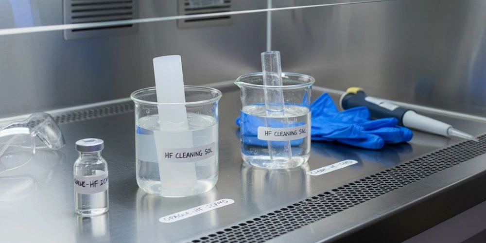
In HF-based wet cleaning, which is the standard method for removing surface contamination and devitrification products from quartz tube bores, the etch rate of fused silica in 1% to 5% HF solutions is approximately 0.3 µm to 0.8 µm per minute at room temperature — effectively identical for both tube types at equivalent HF concentrations. However, the higher surface area of opaque tube internal bores means that a given HF treatment removes a proportionally greater mass of surface material per cleaning cycle, accelerating the rate of wall thickness reduction over successive cleaning cycles. For opaque tubes with initial wall thicknesses of 3 mm to 5 mm, this difference becomes operationally significant after 20 to 40 cleaning cycles, at which point remaining wall thickness should be verified by ultrasonic measurement before continued service in pressure-differential applications.
CVD film adhesion on the internal bore of quartz process tubes is relevant to scheduling of wet cleaning cycles in semiconductor LPCVD operations. The higher Ra of opaque tube inner surfaces (0.4 µm to 1.2 µm) provides greater mechanical interlocking area for deposited films (polysilicon, silicon nitride, TEOS oxide) compared to the smoother transparent tube bore (0.1 µm to 0.4 µm). This increased adhesion delays film spallation — the generation of particles from thermally stressed deposited films during cooling — and extends the interval between wet cleaning cycles by approximately 20% to 40% in polysilicon LPCVD applications, partially compensating for the increased HF etch rate per cleaning event.
HCl gettering — the high-temperature treatment of furnace tube interiors with HCl gas to volatilize and remove adsorbed metal contamination — shows equivalent effectiveness in both tube types when performed under identical conditions (1% to 3% HCl in N₂ at 1,000°C to 1,100°C for 30 to 60 minutes). The additional surface area of the opaque tube bore does not measurably reduce gettering efficiency because HCl transport to all surface sites is diffusion-limited under LPCVD-range flow conditions rather than surface-area-limited.
OH Content Specifications and Their Practical Implications
Hydroxyl group concentration is a shared specification parameter for both tube types, but its performance implications differ significantly between the two depending on the application environment.
Both transparent and opaque quartz tubes are manufactured in low-OH (< 30 ppm) and standard-OH (150 ppm to 400 ppm) grades using the same feedstock and hydroxyl control processes. The effect of OH content on high-temperature devitrification resistance is identical in both tube types: low-OH material delays cristobalite crystallization onset by approximately 150°C relative to standard-OH grades, extending service life at temperatures above 1,000°C from 50 to 80 thermal cycles to 200 to 400 cycles regardless of whether the tube is transparent or opaque.
The critical functional divergence emerges in UV applications, where OH content modifies the short-wavelength transmission cutoff of transparent quartz — a property entirely absent in opaque tubes. For transparent quartz used as UV lamp envelopes, OH content selection involves a trade-off between short-wavelength cutoff (favoring low-OH) and solarization resistance (favoring high-OH synthetic grades). This trade-off does not exist for opaque quartz in any application, because UV transmission is functionally irrelevant to opaque tube performance across its entire application range.
The practical recommendation derived from this analysis: specify OH content based exclusively on operating temperature when selecting opaque quartz tubes — low-OH for sustained service above 900°C, standard-OH for applications below 900°C — without regard to UV considerations. For transparent quartz, OH specification requires simultaneous consideration of operating temperature, UV wavelength range, and required transmission stability over service life.
Chemical Purity and Surface Property Summary
| Property | Opaque Quartz Tube | Transparent Quartz Tube |
|---|---|---|
| Available purity grades (SiO₂) | 99.9% / 99.99% / 99.999% | 99.9% / 99.99% / 99.999% |
| Bulk metallic impurity (same grade) | Equivalent | Equivalent |
| Internal bore Ra (µm) | 0.4–1.2 | 0.1–0.4 |
| Relative surface adsorption area | 1.5–3× baseline | baseline |
| HF etch rate (1–5% HF, RT) | 0.3–0.8 µm/min | 0.3–0.8 µm/min |
| CVD film adhesion (relative) | Higher (+20–40% spallation delay) | Baseline |
| HCl gettering effectiveness | Equivalent | Equivalent |
| Low-OH devitrification onset improvement | +150°C vs. standard-OH | +150°C vs. standard-OH |
| OH content effect on UV transmission | Not applicable | Significant (cutoff shift) |
Dimensional Specifications and Fabrication Tolerances
Standard dimensional ranges and manufacturing tolerances for quartz tube products follow established conventions that apply to both tube types, though the internal void structure introduces modest differences in tolerance achievability at tight specifications.
-
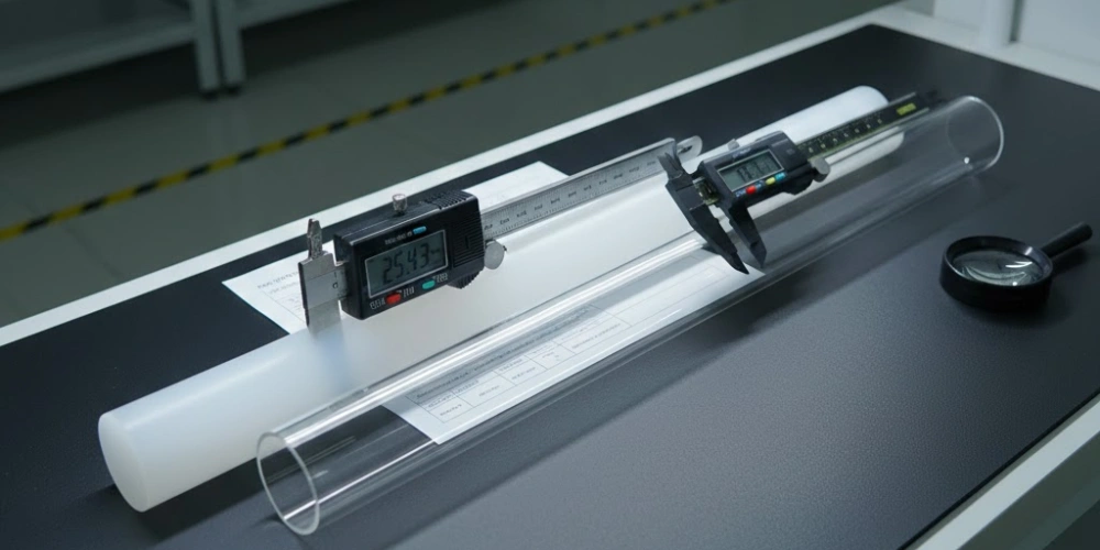
Outer diameter range: Both transparent and opaque quartz tubes are commercially produced in outer diameters from Φ4 mm (small-bore capillary formats) to Φ400 mm or larger (custom semiconductor furnace tubes). Standard catalog outer diameters follow increments of 2 mm to 5 mm in the small-bore range (4 mm to 50 mm) and 10 mm to 25 mm increments above 50 mm OD. Custom ODs outside catalog dimensions are achievable in both tube types through mandrel drawing or centerless grinding, with lead times typically longer for sizes above Φ200 mm.
-
Wall thickness tolerances: Transparent quartz tubes achieve wall thickness tolerances of ±0.2 mm to ±0.5 mm across the standard wall range of 1.5 mm to 8 mm, reflecting the dimensional precision available through the bubble-free fusion drawing process. Opaque quartz tubes, due to the non-uniform void distribution inherent in the flame-fusion process, carry slightly wider wall thickness tolerances of ±0.3 mm to ±0.8 mm at equivalent wall dimensions. For most industrial heating and medical applications, this tolerance difference is inconsequential. For applications requiring close-tolerance bore fits — such as semiconductor furnace tube-to-flange sealing interfaces — the tighter tolerance capability of transparent tube fabrication may favor specification of a transparent tube even if the application would otherwise functionally tolerate opaque material. Internal bore surface roughness (Ra 0.1 µm to 0.4 µm for transparent; 0.4 µm to 1.2 µm for opaque) is a further dimensional parameter affecting sealing and film adhesion performance, as detailed in the preceding section.
-
Length range and axial tolerance: Both tube types are fabricated in standard lengths up to 3,000 mm, with custom lengths achievable by precision cutting to ±1 mm (standard) or ±0.5 mm (precision cut) across both variants. Axial straightness deviation — the maximum bow along the tube length — is specified at ≤1 mm per 1,000 mm of length for both types in standard production, with tighter straightness grades (≤0.5 mm per 1,000 mm) available as a premium specification for semiconductor and precision optical applications.
Dimensional Specification Summary
| Dimensional Parameter | Opaque Quartz Tube | Transparent Quartz Tube |
|---|---|---|
| OD range (mm) | Φ4 to Φ400+ | Φ4 to Φ400+ |
| Wall thickness range (mm) | 1.5–8 | 1.5–8 |
| Wall thickness tolerance | ±0.3 to ±0.8 mm | ±0.2 to ±0.5 mm |
| Internal bore Ra (µm) | 0.4–1.2 | 0.1–0.4 |
| Standard maximum length (mm) | 3,000 | 3,000 |
| Length tolerance (standard cut) | ±1 mm | ±1 mm |
| Axial straightness (standard) | ≤1 mm / 1,000 mm | ≤1 mm / 1,000 mm |
| Axial straightness (precision grade) | ≤0.5 mm / 1,000 mm | ≤0.5 mm / 1,000 mm |
Selection Criteria Across Eight Industrial Application Scenarios
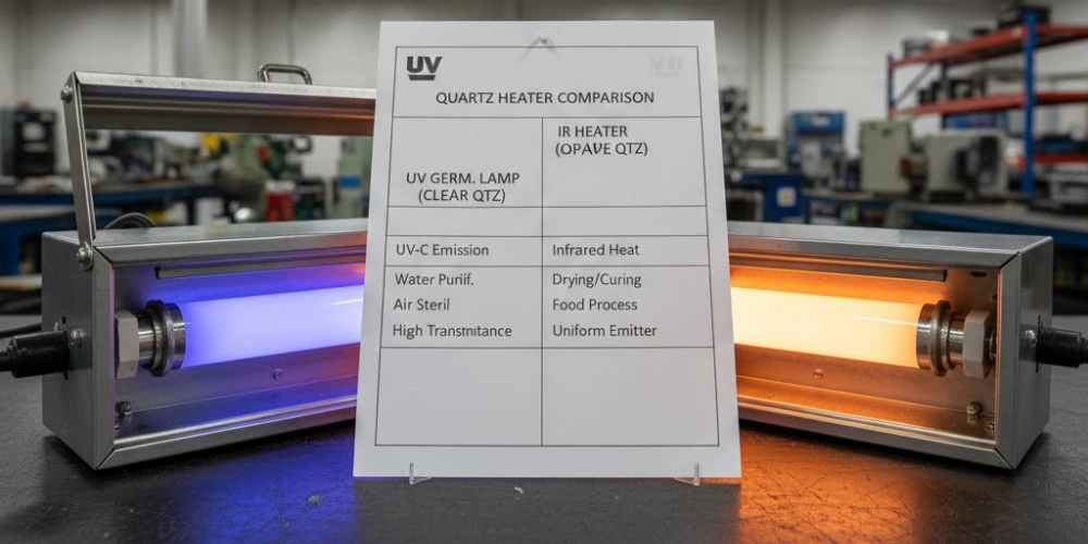
The preceding property comparisons converge in this section into application-specific selection conclusions — the direct answer to the question that motivates most engineers reading this article. Each of the eight scenarios below draws on the quantified property differences established in previous sections to produce a definitive selection recommendation supported by specific performance parameters. Ambiguous middle-ground recommendations are avoided: where the data supports a clear choice, that choice is stated explicitly.
Scenarios Where Opaque Quartz Tubes Are the Definitive Choice
Four application categories exist where opaque quartz tubes deliver performance advantages that transparent alternatives fundamentally cannot match, regardless of purity grade or wall thickness selection.
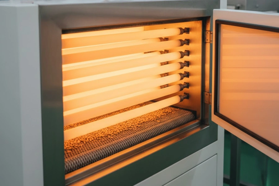
Industrial infrared heating (conveyor ovens, panel heaters, drying tunnels) represents the largest deployment volume for opaque quartz tubes globally. The requirement for spatially uniform irradiance at the product surface — peak-to-average ratio ≤ 1.12 versus 1.4 to 2.1 for transparent tubes — combined with higher MWIR emissivity (ε = 0.90 to 0.95) and 12% to 18% energy efficiency advantage makes opaque tubes the unambiguous choice for any continuous heating application where product surface temperature uniformity is a quality parameter.
UV curing lamp reflective sleeves require simultaneous UV-C blocking (preventing ozone generation and UV-C exposure of non-target materials), diffuse UV-A reflection toward the curing substrate, and thermal isolation of the primary reflector from the lamp arc. All three functions depend on the opacity and internal void scattering of opaque fused silica; transparent quartz fulfills none of these functions and would produce the opposite effect — transmitting UV-C to surrounding components and providing no reflective contribution.
Medical infrared therapy lamps rated at 150 W to 500 W require uniform near-infrared irradiance at the patient treatment surface to prevent localized dermal overheating. Opaque tube emitter geometry eliminates the periodic irradiance modulation inherent in transparent tube heaters, reducing peak irradiance at the skin surface and enabling safe operation at lamp-to-skin distances of 30 cm to 50 cm without hot-spot burn risk.
Food processing infrared ovens (drying, roasting, heat-shrink packaging) specify opaque tubes for the combination of MWIR emission spectrum matched to water and polymer absorption bands, chemical inertness in food-contact-proximate environments, and resistance to alkaline CIP cleaning solutions — a combination of properties that positions opaque fused silica as the standard tube material across food factory infrared heating installations.
Scenarios Where Transparent Quartz Tubes Are the Definitive Choice
An equally clear set of four scenarios exists where transparent quartz tubes are irreplaceable, and where specifying opaque material would result in complete functional failure.
UV germicidal lamp envelopes (low-pressure mercury at 253.7 nm, amalgam lamps, UV-LED coupling tubes) require transmission of ≥ 70% at 253.7 nm through the tube wall to allow the UV-C photon flux generated by the lamp arc to reach the sterilization target zone. An opaque tube transmits less than 5% at this wavelength; installation of an opaque tube as a lamp envelope would reduce germicidal output by more than 93%, rendering the sterilization system non-functional regardless of lamp power input.
Photochemical reactors — used in pharmaceutical synthesis, water treatment by advanced oxidation, and specialty chemical production — require UV or visible radiation to penetrate the tube wall and initiate photochemical reactions within the fluid stream flowing through the tube bore. Transparent quartz tubes with transmission above 80% at 254 nm to 365 nm are the only fused silica component capable of fulfilling this function; opaque tubes provide complete UV blockage and are technically incompatible with photochemical reactor operation.
Semiconductor optical process monitoring in diffusion furnaces equipped with in-situ optical pyrometry or laser interferometry (for oxide thickness measurement) requires a portion of the furnace tube to be optically transparent in the wavelength range of the measurement system — typically 900 nm to 1,100 nm for silicon pyrometry and 632 nm for HeNe laser interferometry. Opaque tube walls block all measurement radiation, making them incompatible with any process tube position that requires optical access to the wafer zone.
UV spectrophotometry and analytical flow cells require transmission across the full UV-A and UV-B measurement range with minimal baseline absorption drift. Transparent synthetic fused silica (Type 4, OH > 800 ppm) provides the lowest solarization-induced transmission drift for sustained analytical lamp service, a performance characteristic entirely inapplicable to opaque tubes.
Mixed Configurations Using Both Tube Types Simultaneously
Several high-performance system designs derive their functional advantages precisely from combining transparent and opaque quartz tubes in the same assembly, exploiting the complementary properties of each.
The standard medium-pressure UV curing lamp assembly is the most widely deployed mixed-tube configuration: a transparent quartz tube forms the lamp envelope (transmitting UV-A, UV-B, and UV-C from the mercury arc plasma), while a coaxially mounted opaque quartz sleeve surrounds it at a 5 mm to 15 mm radial gap (providing diffuse UV-A reflection toward the substrate, blocking UV-C to suppress ozone, and thermally isolating the primary reflector from arc heat). This two-tube configuration achieves UV irradiance at the curing substrate 15% to 25% higher than bare lamp operation while simultaneously eliminating ozone generation and protecting the primary reflector from arc-proximity thermal degradation — a performance combination achievable only through the deliberate pairing of both tube types.
In advanced semiconductor diffusion furnace designs used for processes requiring simultaneous thermal processing and optical monitoring, an opaque outer process tube provides circumferential thermal uniformity (peak-to-average ≤ 1.1 in the wafer zone) while a transparent inner liner tube — positioned within the bore of the opaque outer tube — provides the optical access window required by in-situ measurement systems. The liner tube's high NIR transmission at 900 nm to 1,100 nm is preserved because the opaque outer tube attenuates external thermal radiation rather than blocking the measurement beam path, which travels axially through the transparent liner.
Composite infrared-plus-optical inspection systems in glass forming and automotive glass tempering lines use opaque quartz tube heaters for pre-heating glass blanks while transparent quartz windows or tube sections are incorporated into the same heating module to allow laser profilometry or thermal imaging of the glass surface during the heating sequence — a mixed-tube approach that would be impossible if either tube type were used exclusively.
Eight-Scenario Selection Summary
| Application Scenario | Recommended Tube Type | Primary Selection Parameter |
|---|---|---|
| Industrial infrared conveyor heating | Opaque quartz tube | Emissivity ε = 0.90–0.95; uniformity ratio ≤ 1.12 |
| UV curing reflective sleeve | Opaque quartz tube | UV-A reflectance 60–75%; UV-C blocking < 5% |
| Medical infrared therapy lamp | Opaque quartz tube | Uniform irradiance; peak-to-average ≤ 1.12 |
| Food processing infrared oven | Opaque quartz tube | MWIR emission; chemical inertness; CIP resistance |
| UV germicidal lamp envelope | Transparent quartz tube | UV-C transmission ≥ 70% at 253.7 nm |
| Photochemical reactor tube | Transparent quartz tube | UV/VIS transmission > 80% at process wavelength |
| Semiconductor optical monitoring | Transparent quartz tube | NIR transmission at 900–1,100 nm |
| UV curing lamp assembly (full system) | Both (inner transparent + outer opaque) | Complementary UV transmission + UV-A reflection |
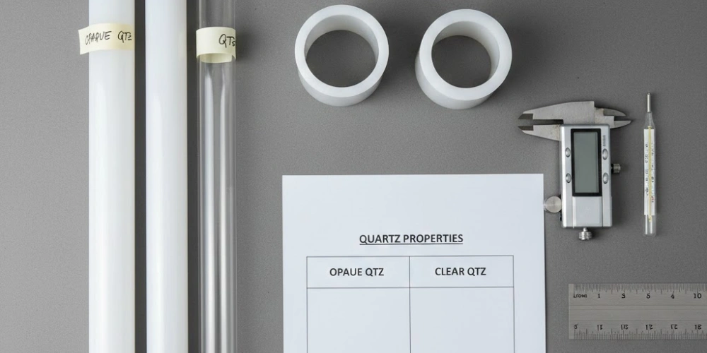
A Condensed Comparison Matrix for Both Tube Materials
For engineers requiring a single consolidated reference across all performance dimensions evaluated in this article, the following table aggregates the quantified specifications of both tube types without reduction or simplification.
-
Chemical and purity equivalence: Both tube types share identical base chemistry (SiO₂ ≥ 99.9% to 99.999%), equivalent CTE (0.55 × 10⁻⁶/°C), and identical maximum service temperature (~1,100°C continuous). Neither tube type holds a bulk purity advantage over the other at equivalent grade specifications.
-
Functional complementarity rather than hierarchy: The performance data compiled in this article does not support the interpretation that one tube type is categorically superior to the other. Transparent quartz tubes are irreplaceable in UV-transmitting applications; opaque quartz tubes are irreplaceable in uniform infrared emission applications. Selecting between them is a matter of matching microstructural optical architecture to application function, not of ranking material quality.
-
The most common specification error encountered in industrial tube procurement is the assumption that transparent quartz tubes are the higher-specification product and opaque tubes a lower-cost substitute. This assumption is incorrect: opaque tubes achieve performance parameters — MWIR emissivity of 0.90 to 0.95, peak-to-average irradiance ratio of 1.05 to 1.12, and UV-C blocking below 5% — that transparent tubes physically cannot match at any price point or purity grade.
Full Material Comparison Matrix
| Performance Parameter | Opaque Quartz Tube | Transparent Quartz Tube |
|---|---|---|
| SiO₂ purity range | 99.9% to 99.999% | 99.9% to 99.999% |
| UV-C transmission (200–280 nm) | < 5% | 70–90% |
| UV-A transmission (315–400 nm) | < 5% | 85–92% |
| Visible transmission (400–700 nm) | < 5% | > 90% |
| NIR transmission (700–2,500 nm) | < 5% | 60–85% |
| MWIR emissivity (ε) | 0.90–0.95 | 0.60–0.75 |
| Radiated power at 900°C (kW/m²) | ~101 | ~75 |
| Peak-to-average irradiance ratio | 1.05–1.12 | 1.4–2.1 |
| CTE (×10⁻⁶/°C) | 0.55 | 0.55 |
| Max continuous service temp (°C) | ~1,100 | ~1,100 |
| Thermal shock fracture rate (1,000°C quench) | 8–12% | 8–12% |
| Low-OH service cycles (> 1,000°C) | 200–400 | 200–400 |
| Internal bore Ra (µm) | 0.4–1.2 | 0.1–0.4 |
| Wall thickness tolerance | ±0.3 to ±0.8 mm | ±0.2 to ±0.5 mm |
| OH content effect on UV performance | Not applicable | Significant |
| Primary exclusive application | Infrared heating; UV sleeve | UV lamp envelope; photochemistry |
Conclusion
Opaque and transparent quartz tubes occupy non-overlapping functional domains despite sharing identical chemical composition and thermal expansion behavior. Opaque quartz tubes deliver superior infrared emissivity, spatial heating uniformity, and UV-C blocking that transparent equivalents cannot replicate. Transparent quartz tubes provide UV transmission windows essential for germicidal lamps, photochemical reactors, and optical process monitoring that opaque variants fundamentally block. Purity grade, OH content, and dimensional tolerances are specifiable in both types without favoring either variant. The selection decision reduces to a single question: does the application require radiation to pass through the tube wall, or to be emitted uniformly from it? That question, answered by the application data rather than convention, produces a defensible specification in every industrial context covered in this article.
FAQ
What is the main functional difference between an opaque quartz tube and a transparent quartz tube?
The central difference is optical architecture. Transparent quartz tubes transmit 70% to 92% of incident UV and visible radiation through the tube wall, making them essential for UV lamp envelopes and photochemical reactors. Opaque quartz tubes transmit less than 5% across the UV, visible, and NIR spectrum, instead absorbing and re-emitting radiation as diffuse infrared from the outer surface at emissivity ε = 0.90 to 0.95. This produces spatially uniform infrared heating and UV-C blocking — properties transparent tubes cannot provide.
Does the internal void structure of opaque quartz tubes reduce their purity or thermal shock resistance compared to transparent tubes?
Neither. ICP-MS analysis of matched production batches confirms no statistically significant difference in bulk metallic impurity concentrations between the two tube types at equivalent purity grades. Thermal shock fracture testing — immersion from 1,000°C into 25°C water — produces equivalent fracture rates of 8% to 12% in both variants. The internal voids do not act as effective Griffith fracture initiation sites under normal industrial thermal cycling conditions because their maximum diameter (100 µm) falls below the critical defect size threshold for the thermal stress levels encountered in service.
Which tube type should be specified for a semiconductor diffusion furnace process tube?
The answer depends on whether the furnace includes in-situ optical monitoring. For standard thermal oxidation, annealing, and LPCVD processes without optical access requirements, opaque quartz process tubes are preferred because their higher MWIR emissivity and scattering-induced uniformity produce superior wafer-zone temperature uniformity (±1°C to ±2°C). For furnace configurations incorporating in-situ optical pyrometry or laser interferometry at NIR wavelengths (900 nm to 1,100 nm), transparent quartz must be used at the measurement access position — or a mixed transparent-inner-liner plus opaque-outer-tube configuration must be adopted.
Can opaque and transparent quartz tubes be used together in the same system?
Yes — and several high-performance system designs depend on this combination. The most common example is the medium-pressure UV curing lamp assembly, in which a transparent quartz lamp envelope (transmitting UV-A, UV-B, and UV-C from the mercury arc) is surrounded by an opaque quartz reflective sleeve (providing diffuse UV-A reflection toward the curing substrate, suppressing UV-C ozone generation, and thermally isolating the primary reflector). This configuration achieves UV irradiance gains of 15% to 25% at the curing surface compared to bare lamp operation — a performance level unachievable with either tube type deployed alone.
References:
-
Flame hydrolysis is a vapor-phase synthesis process in which silicon tetrachloride is oxidized in a hydrogen-oxygen flame to produce high-purity amorphous silicon dioxide soot, widely used as the primary feedstock for synthetic fused silica production. ↩
-
Griffith crack theory is a foundational framework in fracture mechanics establishing that brittle materials fracture when the strain energy released by crack propagation exceeds the surface energy required to create new crack faces, with critical fracture stress scaling inversely with the square root of the largest pre-existing defect dimension. ↩
-
A color center is a lattice defect in an otherwise transparent crystalline or glass material that absorbs visible or UV light, produced in fused silica by high-energy photon exposure and responsible for the transmission degradation observed in UV lamp quartz envelopes. ↩