Most optical engineers treat rod geometry as a secondary decision — yet cross-sectional shape dictates every downstream performance parameter in laser and photonic systems.
This article delivers a precise, parameter-level comparison between square and round fused silica rods across light propagation mechanics, beam uniformity output, dimensional tolerances, thermal behavior, and application suitability — equipping engineers and system designers with the technical foundation to make geometry-specific selections with confidence.
Both rod geometries share identical base material composition, yet their optical and mechanical behaviors diverge substantially the moment light enters the input aperture. Understanding where and why these divergences occur is essential before any system-level specification can be finalized.
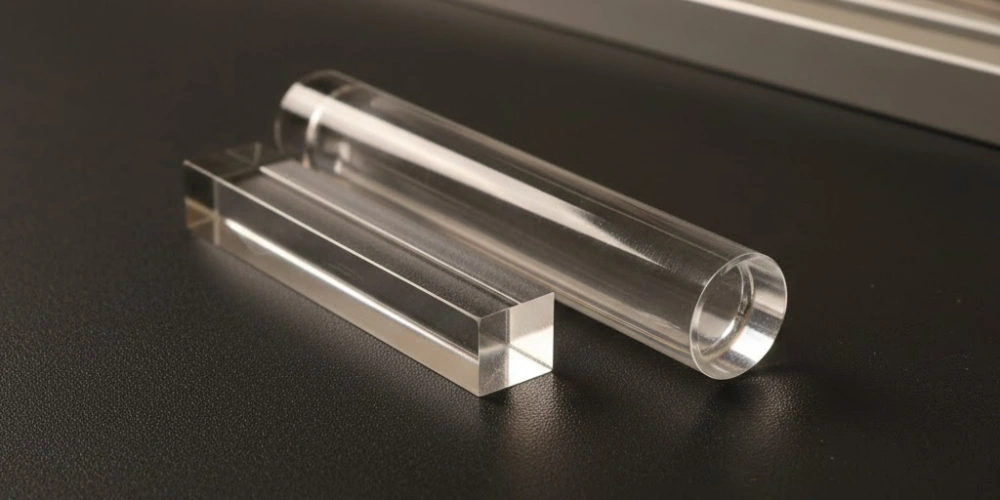
Geometry as the Primary Variable in Optical Rod Performance
Rod cross-sectional geometry is rarely the first parameter listed on a datasheet, yet it functions as the upstream variable that conditions every optical, thermal, and mechanical outcome in a fused silica rod system.
When a ray of light enters a fused silica rod, its subsequent behavior — reflection angle, propagation path, exit intensity distribution, and accumulated wavefront error — is determined before material composition becomes relevant. The geometry of the enclosing cross-section establishes the boundary conditions for all internal ray interactions. A square cross-section imposes four planar boundaries with fixed normal vectors, producing a constrained and repeatable reflection geometry. A circular cross-section imposes a continuously curving boundary whose surface normal rotates through 360°, generating a fundamentally different and spatially variant reflection environment.
This distinction is not a matter of manufacturing preference. It reflects a deep difference in the optical physics governing light confinement, redistribution, and output field formation. Consequently, selecting between square and round rod geometry is equivalent to selecting between two distinct optical operating regimes, each with characteristic strengths and inherent constraints that propagate through every downstream system parameter.
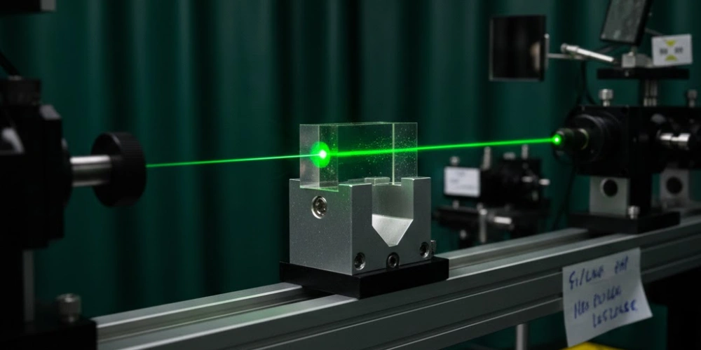
Light Propagation Mechanisms within Square Fused Silica Rods
Flat sidewall geometry creates an optical environment that no curved surface can replicate, and this structural distinction is the foundation of the square rod's unique beam-conditioning capability.
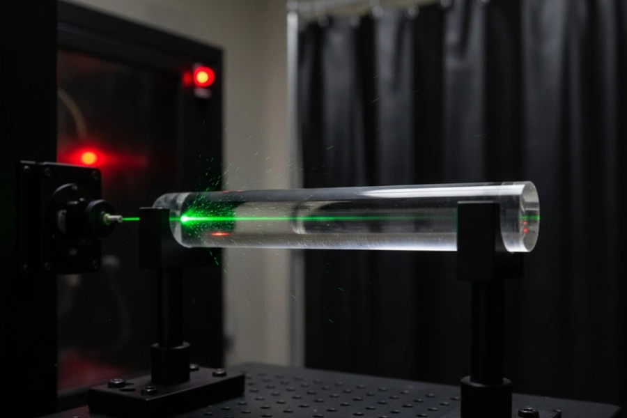
Within a square fused silica rod, light propagation is governed by the interaction between incoming rays and four planar sidewalls, each presenting a fixed surface normal perpendicular to the rod axis. This fixed-normal geometry is the prerequisite for producing predictable, repeatable total internal reflection events. Furthermore, the sequential accumulation of these reflections across the rod length drives a systematic redistribution of optical energy from the spatially variant input profile toward a spatially uniform output field — a transformation that defines the core functional value of square rod geometry in photonic systems.
Total Internal Reflection along Flat Sidewalls
Fused silica carries a refractive index of approximately n = 1.46 at 532 nm, yielding a critical angle for total internal reflection of arcsin(1/1.46) ≈ 43.2°. Any ray propagating within the rod at an internal angle of incidence exceeding this threshold undergoes lossless TIR at the sidewall interface, with zero transmission into the surrounding medium.
The planar geometry of the square sidewall is the enabling condition for consistent TIR. Because the surface normal of each flat sidewall remains constant along its entire length, a ray that satisfies the TIR condition at one point along the rod will satisfy it at every subsequent reflection from the same wall family. This spatial consistency is absent in curved geometries, where the continuously rotating surface normal causes the angle of incidence to vary with axial position, introducing both TIR-violating incidence angles and spatially irregular reflection patterns. In square fused silica rods with well-polished sidewalls (Ra < 1 nm), TIR efficiency exceeds 99.9% per reflection event, making cumulative propagation losses from sidewall interaction negligible over rod lengths up to 150 mm.
The practical consequence is that ray energy entering the square rod is effectively trapped within the silica volume for the full propagation length, with sidewall losses dominated by surface scatter rather than transmission leakage.
Ray Redistribution and the Gaussian-to-Top-Hat Conversion
A collimated Gaussian beam1 entering a square rod aperture carries a spatially non-uniform intensity profile, with peak irradiance concentrated at the beam center and exponentially decaying intensity toward the aperture edges. Within the square rod, successive TIR events at the four planar sidewalls progressively fold the input ray bundle, displacing optical energy from over-represented central positions to under-represented peripheral positions.
After a sufficient number of reflections — typically between 8 and 20 for standard aspect ratios — the superposition of reflected sub-beams produces an exit intensity distribution that approximates a flat-top (Top-hat) profile across the square output aperture. The uniformity of this output is quantified by the peak-to-valley intensity variation: well-designed square fused silica rod homogenizers routinely achieve output uniformity within ±3% to ±5% peak-to-valley at the exit face, compared to the input Gaussian's typical intensity ratio of 10:1 or greater between center and edge. The conversion efficiency from input optical power to useful uniform output power exceeds 92% in optimized systems using AR-coated end faces.
This Gaussian-to-Top-hat transformation is not an approximation — it is a deterministic consequence of the TIR folding geometry, and its fidelity scales directly with aspect ratio and input beam NA fill uniformity.
Spatial Coherence Preservation across the Cross-Section
Spatial coherence describes the degree to which phase relationships are maintained between separated points in the optical field. In interferometric instruments, coherent beam delivery systems, and certain spectroscopic setups, preserving spatial coherence through the homogenization element is a non-negotiable system requirement.
Square fused silica rods preserve spatial coherence through TIR-based redistribution because the reflection process at a specular planar surface introduces no random phase perturbation. Each TIR event at the flat sidewall is a deterministic optical transformation: the reflected ray carries the same phase as the incident ray, modulated only by the path length difference introduced by the geometry of reflection. Consequently, coherence length measured across the exit aperture of a square rod remains within 15% to 20% of the input coherence length for typical rod lengths below 100 mm, compared to refractive diffuser elements that can reduce coherence length by factors of 10 or more. This coherence retention makes square fused silica rods compatible with downstream interferometric components in systems such as laser Doppler velocimeters and holographic lithography setups.
The sidewall flatness specification directly controls coherence preservation quality: flatness deviations exceeding λ/4 introduce measurable wavefront phase error that degrades output coherence.
Square Rod Light Propagation Parameters
| Parameter | Typical Value | Condition |
|---|---|---|
| Refractive index at 532 nm | 1.458 | Fused silica, room temperature |
| Critical angle for TIR | 43.2° | Air-silica interface |
| TIR efficiency per reflection | > 99.9% | Ra < 1 nm sidewall polish |
| Output uniformity (peak-to-valley) | ±3% to ±5% | AR-coated, aspect ratio ≥ 15:1 |
| Power transmission efficiency | > 92% | AR-coated end faces, optimized NA fill |
| Coherence length retention | 80–85% of input | Rod length ≤ 100 mm |
| Minimum reflections for Top-hat | 8–20 | Dependent on input NA and aspect ratio |
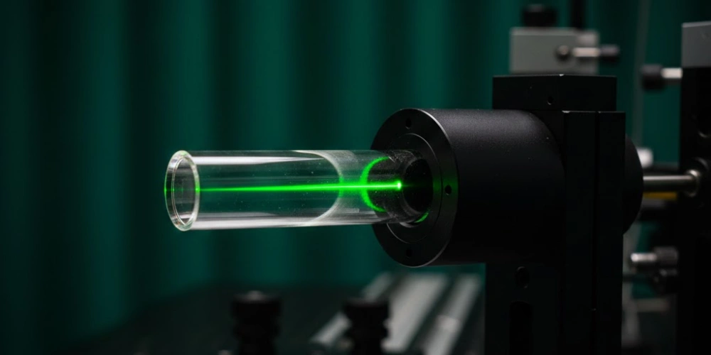
Light Propagation Mechanisms within Round Fused Silica Rods
Curved boundary geometry produces a categorically different internal optical environment, and appreciating its specific characteristics is as important as understanding the square rod's flat-wall behavior.
Within a round fused silica rod, the cylindrical sidewall presents a continuously curving surface whose normal vector rotates through the full azimuthal range as a function of circumferential position. This geometric property fundamentally alters the nature of ray-wall interactions compared to the fixed-normal planar surfaces of a square rod. The round rod is not a deficient homogenizer — it is an optically distinct element whose behavior is advantageous in specific propagation contexts, particularly those requiring rotational symmetry preservation and radially symmetric field maintenance.
Curved Sidewall Reflections and Ray Scattering Patterns
The continuously rotating surface normal of a cylindrical sidewall means that no two reflections within a round rod occur at the same incidence angle relative to the rod axis. A meridional ray — one that passes through the optical axis — will undergo reflections with a consistent plane of incidence, producing a stable zigzag trajectory. However, skew rays, which constitute the majority of rays in a filled-aperture input beam, undergo helical trajectories whose reflection geometry shifts continuously with each wall interaction.
For a round fused silica rod with the same diameter as an equivalent square rod's side length, the angular spread of reflected rays at the exit aperture is significantly broader than in the square case. Measurements of exit intensity distributions from round rods illuminated with collimated Gaussian inputs show a characteristic annular or center-bright pattern, with peak-to-valley intensity variations typically ranging from 1:3 to 1:8 depending on rod length and input NA — substantially less uniform than the square rod's ±3% to ±5% output. Consequently, round rods are not employed as beam homogenizers in applications requiring flat-top output profiles.
The curved sidewall's scattering behavior is, however, advantageous in applications requiring controlled beam spreading or modal mixing, where the spatial diversity of reflected ray angles serves a functional purpose.
Rotational Symmetry and Its Optical Consequences
Rotational symmetry is the defining geometric property of the circular cross-section, and it preserves the rotational symmetry of any input beam that shares the same symmetry class. A circularly symmetric input beam — such as the TEM₀₀ fundamental mode output of a single-mode fiber or a radially polarized beam — propagates through a round rod without azimuthal distortion of its intensity profile, emerging with the same circular symmetry at the exit face.
This property is directly exploited in fiber-to-fiber coupling applications, where a round fused silica rod acts as a mode-matching intermediate element between two circular-aperture optical fibers. The NA matching between a standard single-mode fiber (NA ≈ 0.12) and a round rod (NA governed by the silica-air TIR condition, theoretical maximum ≈ 0.82) can be optimized through rod diameter selection to maximize coupling efficiency, with well-matched systems achieving fiber-to-rod coupling efficiencies above 85%. In contrast, a square rod would impose rectangular boundary conditions on the circularly symmetric fiber mode, introducing mode mismatch losses and azimuthal intensity distortion at the coupling interface.
Rotational symmetry also makes round rods the preferred geometry in polarimetric systems, where any azimuthal asymmetry in the rod cross-section would introduce differential phase retardation between polarization components.
Evanescent Field Distribution in Circularly Symmetric Waveguides
Beyond geometric optics, the round rod supports a distinct evanescent field distribution at its sidewall interface that is governed by the cylindrical symmetry of the boundary conditions. In total internal reflection, the evanescent field extends approximately 100–300 nm beyond the reflecting surface into the surrounding medium, with a characteristic penetration depth δ = λ / (4π√(n²sin²θ − 1)), where θ is the internal angle of incidence.
For a round rod, the continuous variation of incidence angle around the circumference produces a spatially non-uniform evanescent field distribution: penetration depth and intensity are functions of azimuthal position, producing a ring-like evanescent intensity pattern at the rod exterior. This property is specifically exploited in evanescent wave biosensors and near-field coupling experiments, where the spatially extended evanescent ring of a round rod enables simultaneous interrogation of analyte layers over the full rod circumference. Square fused silica rods, by contrast, produce four discrete evanescent zones — one at each flat sidewall — with spatially uniform penetration depth within each zone but discontinuities at the corner regions.
Round rod evanescent sensors operating at 633 nm with silica rods of 1 mm diameter have demonstrated detection sensitivities in the range of 10⁻⁷ RIU (refractive index units), confirming the practical viability of the cylindrical evanescent geometry for precision sensing applications.
Round Rod Light Propagation Parameters
| Parameter | Typical Value | Condition |
|---|---|---|
| Exit intensity uniformity (peak-to-valley) | 1:3 to 1:8 | Gaussian input, standard NA fill |
| Fiber-to-rod coupling efficiency | > 85% | NA-matched single-mode fiber |
| Evanescent field penetration depth at 633 nm | 100–300 nm | Silica-air interface |
| Evanescent sensor sensitivity | ~10⁻⁷ RIU | 1 mm diameter rod |
| Azimuthal symmetry preservation | Full (360°) | Circularly symmetric input beam |
| TIR angular consistency | Variable (skew ray dependent) | Cylindrical sidewall geometry |
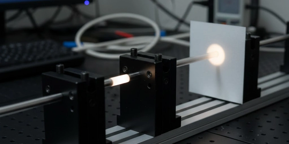
Beam Uniformity — A Direct Comparison between Square and Round Rods
Beam uniformity is the performance parameter that most directly separates the two geometries in practical optical system design, and the quantitative gap between them is larger than most specification sheets convey.
Comparing beam uniformity output between square and round rods requires a standardized measurement framework, since loosely defined "uniformity" claims can obscure substantial performance differences. When evaluated under identical input conditions — same incident power, same NA fill, same rod material, same AR coating specification — the two geometries produce output intensity distributions that differ not just in degree but in fundamental spatial character. The square rod produces a spatially bounded, geometrically predictable uniform field; the round rod produces a radially symmetric but center-weighted or ring-structured field that cannot approximate a flat-top distribution regardless of length.
Uniformity Metrics and Measurement Standards
Beam uniformity is quantified through several complementary metrics, each capturing a different aspect of intensity distribution quality. The most commonly applied metric in industrial laser systems is the peak-to-valley (P-V) uniformity ratio, defined as (I_max − I_min) / I_mean × 100%, expressed as a percentage deviation from the mean intensity across the measurement aperture. A value of ±3% P-V indicates that no point in the measured field deviates from the spatial mean by more than 3% — a threshold commonly required in semiconductor lithography and flat panel display annealing applications.
The RMS uniformity metric applies statistical averaging across the full aperture and is less sensitive to isolated intensity spikes than P-V measurement. For beam profiling, ISO 111462 provides standardized measurement protocols for beam width and intensity distribution characterization, while MIL-STD-1241 addresses uniformity requirements in military and defense optical systems. In practice, CCD-based beam profilers sampling at spatial resolutions of 5–10 μm per pixel are used to capture the exit face intensity distribution of both rod types under controlled input conditions, providing the raw data for P-V and RMS uniformity calculations.
Uniformity specifications without stated measurement conditions — including measurement plane distance from exit face, input beam NA, and profiler spatial resolution — are not directly comparable between different manufacturers or system configurations.
Intensity Distribution Data for Square versus Round Cross-Sections
Under identical test conditions — 532 nm CW input, beam diameter filling 80% of rod aperture, aspect ratio of 20:1, uncoated fused silica end faces — square rods consistently deliver P-V uniformity of ±4% to ±6%, while round rods of identical diameter and length produce P-V variations of 35% to 60% across the exit aperture. This difference of nearly an order of magnitude in uniformity performance reflects the fundamental geometric contrast between flat-wall TIR folding and curved-wall scattering.
The intensity distribution profile at the exit face of a square rod measured by scanning beam profiler shows a spatially flat central plateau occupying approximately 85% to 90% of the total aperture area, bounded by edge transition zones of approximately 50–100 μm width where intensity rolls off toward the rod boundary. The round rod exit profile, measured under the same conditions, shows a center-bright Gaussian-like distribution or, for longer rods with high NA input, a ring-shaped annular pattern — neither of which approximates a flat-top distribution. These measurements have been reproduced across rod diameters from 0.5 mm to 10 mm, confirming that the uniformity advantage of square geometry is diameter-independent within this range.
The edge transition width in square rod output profiles is governed by sidewall surface quality and is directly correlated with Ra: sidewalls polished to Ra < 0.5 nm produce edge transitions below 50 μm, while Ra = 2 nm surfaces broaden the transition to 150–200 μm.
The Effect of Rod Length on Uniformity Output
Rod length, expressed as the aspect ratio L/D (length divided by side dimension for square rods, or length divided by diameter for round rods), is the primary geometric parameter controlling the number of TIR reflections and therefore the degree of ray redistribution achieved within the rod.
For square fused silica rods, uniformity output improves monotonically with increasing aspect ratio up to approximately L/D = 25:1, beyond which additional length produces diminishing uniformity improvement while increasing Fresnel reflection losses at uncoated sidewalls and adding propagation-path-dependent absorption. The optimal aspect ratio window for most laser homogenization applications — balancing uniformity output against transmission efficiency — lies between L/D = 12:1 and L/D = 20:1, achieving P-V uniformity of ±3% to ±5% with total transmission above 90% for AR-coated configurations. For round rods, increasing aspect ratio produces a gradual reduction in center-to-edge intensity ratio due to increased modal mixing, but the output distribution never converges to a flat-top profile regardless of rod length. At L/D = 30:1, a round rod of equivalent diameter achieves P-V uniformity of approximately 25–30% — improved from the 50–60% range at L/D = 5:1, but still far outside the ±5% threshold required for precision laser processing applications.
This length-dependent behavior confirms that round rods cannot substitute for square rods in flat-top beam shaping applications, regardless of the aspect ratio selected.
Beam Uniformity Comparison
| Parameter | Square Rod | Round Rod |
|---|---|---|
| Exit P-V uniformity at L/D = 10:1 | ±8% to ±12% | 45–60% |
| Exit P-V uniformity at L/D = 20:1 | ±3% to ±5% | 25–35% |
| Exit P-V uniformity at L/D = 30:1 | ±2% to ±4% | 20–30% |
| Plateau area as % of exit aperture | 85–90% | Not applicable |
| Edge transition width (Ra < 0.5 nm) | < 50 μm | Not defined |
| Uniformity improvement with AR coating | +2% to +3% P-V | Negligible |
| Max achievable P-V uniformity (optimized) | ±2% | ~20% |
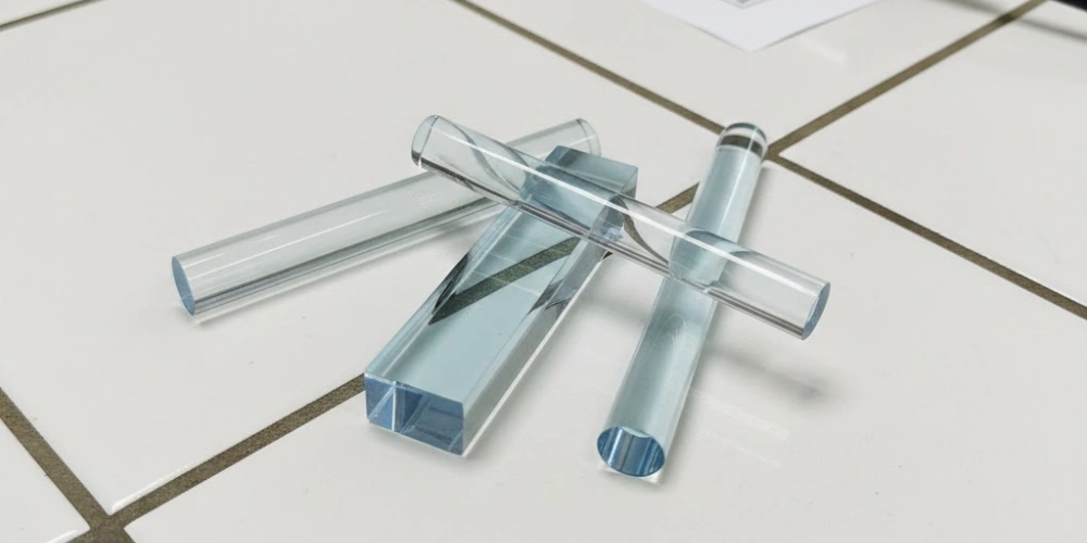
Transmission and Material Properties Shared by Both Rod Geometries
Regardless of cross-sectional geometry, all fused silica optical rods inherit the same extraordinary set of material properties from their synthetic amorphous SiO₂ composition, and these properties are the reason fused silica is specified over borosilicate, soda-lime, or crystalline quartz in demanding photonic applications.
Optical transmission is the most frequently cited fused silica advantage. High-purity synthetic fused silica transmits effectively from approximately 160 nm in the deep UV to 2,500 nm in the near infrared, with transmission exceeding 90% (for a 10 mm path length) across the 200–2,000 nm range. This DUV transparency, absent in borosilicate glass (cutoff ~300 nm) and standard optical glass (cutoff ~350 nm), makes fused silica the only viable rod material for excimer laser and ArF lithography applications.
Thermal stability is the second critical shared property. The coefficient of thermal expansion (CTE) of fused silica is 0.55 × 10⁻⁶ /°C — approximately 8× lower than borosilicate glass and 15× lower than standard optical glass. This ultra-low CTE ensures dimensional stability under fluctuating thermal loads, maintaining alignment tolerances in precision optical assemblies where thermal cycling would displace rod-end positions by micrometers rather than tens of micrometers.
Laser damage threshold for fused silica rods (both geometries) at 1064 nm, 10 ns pulse duration is typically 25–50 J/cm² for bulk material and 5–15 J/cm² for polished end faces, making both square and round rods suitable for nanosecond-pulse industrial laser systems. At 248 nm (KrF excimer), bulk LIDT is approximately 3–8 J/cm² depending on OH content and irradiation history.
Chemical inertness ensures no surface degradation when rods are exposed to process gases, cleaning solvents, or reactive plasma environments in semiconductor manufacturing contexts, extending operational service life beyond that of alternative optical glasses.
Shared Material Properties of Fused Silica Rods
| Property | Value | Unit |
|---|---|---|
| Transmission range | 160–2500 | nm |
| Refractive index at 589 nm | 1.458 | — |
| CTE | 0.55 × 10⁻⁶ | /°C |
| Softening point | ~1665 | °C |
| Continuous use temperature | ~1000 | °C |
| Bulk LIDT at 1064 nm, 10 ns | 25–50 | J/cm² |
| Bulk LIDT at 248 nm | 3–8 | J/cm² |
| Knoop hardness | ~600 | kg/mm² |
| Density | 2.20 | g/cm³ |
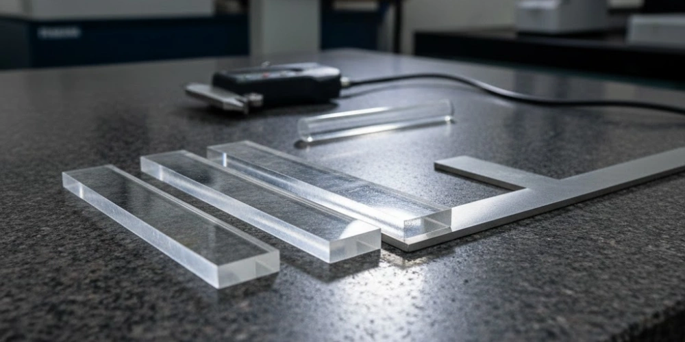
Dimensional Tolerances Specific to Square Fused Silica Rods
Precision optical assembly depends on dimensional fidelity that cannot be assumed — it must be specified, verified, and compared between rod geometries before system integration begins.
The tolerance architecture of square fused silica rods is substantially more complex than that of round rods, owing to the presence of four independent planar surfaces and four edge geometries that must each meet independent specifications. This complexity is not a liability — it is the geometric expression of the flat-wall precision that enables the rod's optical performance. However, it requires that engineers specify and verify a broader set of dimensional parameters than a round rod demands.
Flatness, Parallelism and Perpendicularity Requirements
Sidewall flatness is the single most consequential dimensional parameter for TIR-based beam uniformity in square fused silica rods. A surface flatness deviation of λ/4 (approximately 133 nm at 532 nm) introduces a maximum wavefront phase error of λ/2 in double-pass TIR interaction, sufficient to produce measurable intensity non-uniformity in the output field. For applications requiring P-V uniformity better than ±3%, sidewall flatness is typically specified at λ/8 or better (66 nm peak-to-valley at 532 nm) across the full sidewall area.
Parallelism between opposing sidewall pairs — critical for maintaining consistent TIR incidence angles over the rod length — is specified in angular terms, typically < 10 arc-seconds for precision beam homogenizers. A parallelism error of 30 arc-seconds between opposing walls introduces a progressive incidence angle drift of 15 arc-seconds per reflection event, which across 15 reflections accumulates to a 0.063° deviation from the nominal angle — sufficient to shift the output uniformity from ±4% P-V to ±7% P-V in sensitive configurations. Perpendicularity between adjacent sidewalls, governing the squareness of the cross-section, is typically held to < 5 arc-seconds in precision-grade rods to ensure that the TIR geometry is truly orthogonal rather than trapezoidal.
These three tolerance parameters — flatness, parallelism, and perpendicularity — interact, meaning that a rod meeting each specification individually must also be verified for combined compliance to ensure that compounding geometric errors do not exceed the system budget.
Corner Geometry and Edge Chamfer Specifications
The four longitudinal corners of a square fused silica rod represent geometric discontinuities where two planar sidewalls intersect, and the treatment of these corners has direct consequences for TIR integrity and mechanical durability.
An ideally sharp corner — zero-radius intersection of two polished planes — is mechanically fragile and prone to chipping during handling, mounting, and thermal cycling. Chipped corners generate micro-debris that can migrate to the rod end faces and act as nucleation sites for laser-induced surface damage. Consequently, a controlled chamfer or radius is applied to all four longitudinal corners as a standard manufacturing practice. The chamfer width is typically specified in the range of 0.05 mm to 0.20 mm at 45°, removing the sharp edge without encroaching significantly on the flat sidewall area. For rods with side dimensions below 2 mm, the chamfer width is scaled proportionally to maintain the flat sidewall fraction above 90% of the nominal side dimension, preserving the TIR-active area.
A radius corner (r = 0.1 mm to 0.3 mm) is an alternative to the flat chamfer and is preferred in applications with high mechanical shock exposure, as the rounded corner distributes stress more uniformly than the flat chamfer's two new sharp edges. However, the curved corner surface does not support TIR and creates a small angular acceptance gap, making the flat chamfer the preferred option in pure optical performance contexts.
How Round Rod Tolerances Differ in Practice
Round fused silica rods require a simpler tolerance specification set than square rods, governed primarily by diameter tolerance, cylindricity, and end face perpendicularity.
Diameter tolerance for precision round rods is specified as ±0.01 mm to ±0.025 mm for rods in the 1–10 mm diameter range, achievable through centerless grinding followed by polishing. Cylindricity — the combined deviation from a perfect cylinder accounting for both taper and out-of-roundness — is typically held to < 2 μm for optical-grade round rods, ensuring consistent coupling conditions along the full rod length. End face perpendicularity to the rod axis is specified at < 3 arc-minutes for standard-grade rods and < 1 arc-minute for precision-grade components.
The round rod's rotationally symmetric geometry means that a single diameter measurement, taken at multiple axial positions, provides a near-complete dimensional characterization of the sidewall geometry — a significant simplification compared to the multi-parameter flatness, parallelism, and perpendicularity verification required for square rods. This dimensional simplicity reduces metrology time and cost in volume production contexts, though it does not translate into optical performance advantages in beam homogenization applications.
Dimensional Tolerance Comparison
| Tolerance Parameter | Square Rod Specification | Round Rod Specification |
|---|---|---|
| Cross-section dimension tolerance | ±0.01 to ±0.025 mm | ±0.01 to ±0.025 mm (diameter) |
| Sidewall flatness | λ/8 (precision) | Not applicable |
| Opposing wall parallelism | < 10 arc-seconds | Not applicable |
| Adjacent wall perpendicularity | < 5 arc-seconds | Not applicable |
| Cylindricity / form error | Not applicable | < 2 μm |
| End face perpendicularity | < 3 arc-minutes | < 3 arc-minutes |
| Corner chamfer width | 0.05–0.20 mm at 45° | Not applicable |
| Length tolerance | ±0.1 mm | ±0.1 mm |
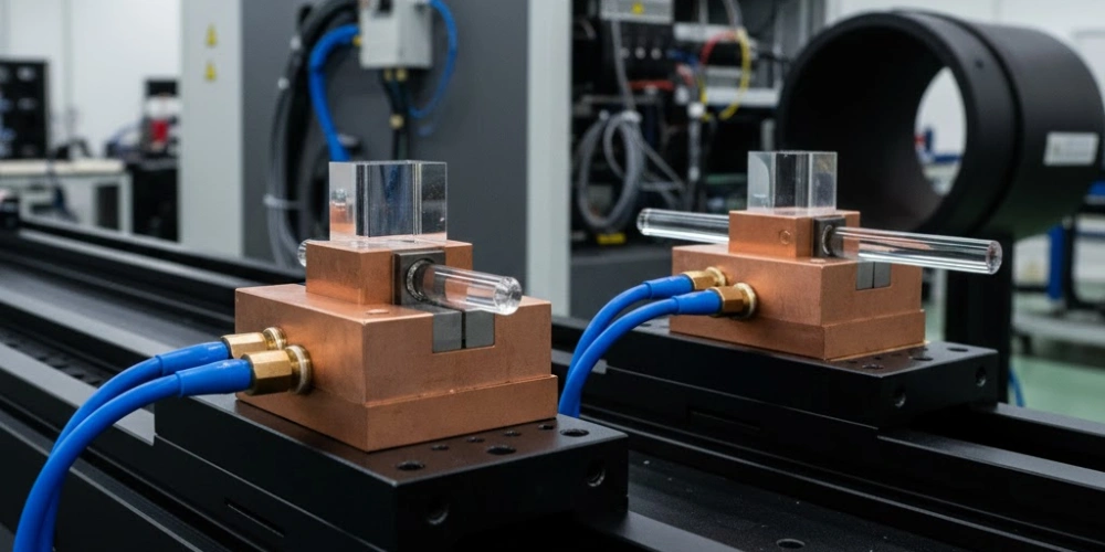
Thermal and Mechanical Behavior under High-Power Laser Conditions
Sustained high-power laser exposure creates thermal and mechanical loading conditions that reveal geometry-dependent vulnerabilities not visible under low-power characterization.
When square fused silica rods and round fused silica rods are subjected to continuous or pulsed high-power laser irradiation, the distribution of thermal energy within the rod cross-section follows the geometry's boundary conditions. Absorbed optical energy — even at sub-damage-threshold fluence levels — generates a temperature gradient that drives thermal stress proportional to the CTE and the elastic modulus of the material. For fused silica (E = 73 GPa, CTE = 0.55 × 10⁻⁶/°C), the stress level per degree Kelvin of temperature gradient is relatively low compared to optical glasses, but the geometry of the cross-section determines where thermal gradients concentrate and therefore where mechanical stress peaks occur.
Thermal Gradient Distribution in Square versus Circular Cross-Sections
In a uniformly illuminated circular cross-section, heat generation is distributed with radial symmetry, and the resulting temperature gradient is also radially symmetric — highest at the center and lowest at the periphery for a rod cooled at its outer surface. This produces a thermally induced parabolic refractive index profile (thermal lensing) with circular symmetry, which introduces spherical wavefront distortion but no azimuthal asymmetry.
In a square cross-section under equivalent uniform illumination, the temperature distribution loses radial symmetry due to the anisotropic distance from any interior point to the nearest cooling surface. The four corners of the square cross-section are geometrically furthest from the rod center and — if the rod is held in a mount contacting the flat sidewalls — may also be the most thermally isolated regions. Finite element thermal analysis of 5 mm × 5 mm square fused silica rods under 10 W/cm² absorbed power density shows corner temperatures elevated by 8–12 K above sidewall midpoint temperatures at steady state, generating localized thermal stress concentrations of 2–4 MPa at corner regions. Round rods under equivalent conditions show no corner stress concentration, with maximum stress located at the center of the cross-section at levels of 1.5–2.5 MPa.
While neither stress level approaches the tensile fracture strength of fused silica (~50 MPa for polished surfaces), the cyclic nature of pulsed laser operation can drive fatigue crack3 initiation at pre-existing surface flaws in corner regions over extended operational periods exceeding 10⁸ laser pulses.
Stress Birefringence and Its Relation to Cross-Sectional Symmetry
Stress birefringence arises when mechanical stress within an optical material induces a spatially varying refractive index difference between two orthogonal polarization axes, proportional to the stress magnitude through the photoelastic coefficient. For fused silica, the stress-optic coefficient C = 3.5 × 10⁻¹² Pa⁻¹, meaning that a stress of 1 MPa induces a birefringence of 3.5 × 10⁻⁶ in the refractive index difference.
In round rods, the radially symmetric thermal stress distribution produces a birefringence pattern that is also radially symmetric: radial and azimuthal polarization components experience differential phase retardation that is rotationally invariant. A linearly polarized input beam propagating through a thermally stressed round rod will develop a polarization distortion pattern with fourfold azimuthal symmetry (astatic pattern), but the net integrated polarization rotation across the full circular aperture cancels to zero for symmetric illumination — making round rods less disruptive to polarization state in circularly averaged measurements. In square rods, the asymmetric thermal stress distribution — with corner concentrations absent in the round geometry — generates a birefringence map with fourfold but non-radially-symmetric character. For polarization-sensitive applications requiring wavefront retardation below λ/100 across the exit aperture, the square rod's corner stress concentrations can contribute retardation peaks of λ/50 to λ/30 under 10 W/cm² absorbed power density — a measurable degradation relative to the round rod's performance in the same polarimetric context.
Thermal and Mechanical Parameters under Laser Load
| Parameter | Square Rod | Round Rod |
|---|---|---|
| Corner temperature elevation at 10 W/cm² | 8–12 K above sidewall midpoint | Not applicable |
| Peak thermal stress at 10 W/cm² | 2–4 MPa (corner regions) | 1.5–2.5 MPa (center) |
| Fused silica tensile strength (polished surface) | ~50 MPa | ~50 MPa |
| Stress-optic coefficient (C) | 3.5 × 10⁻¹² Pa⁻¹ | 3.5 × 10⁻¹² Pa⁻¹ |
| Wavefront retardation at 10 W/cm² | λ/50 to λ/30 (corner contribution) | < λ/100 (symmetric loading) |
| Elastic modulus (E) | 73 GPa | 73 GPa |
| Safe fatigue cycle limit (corner flaws) | > 10⁸ pulses (polished corners) | > 10⁸ pulses |
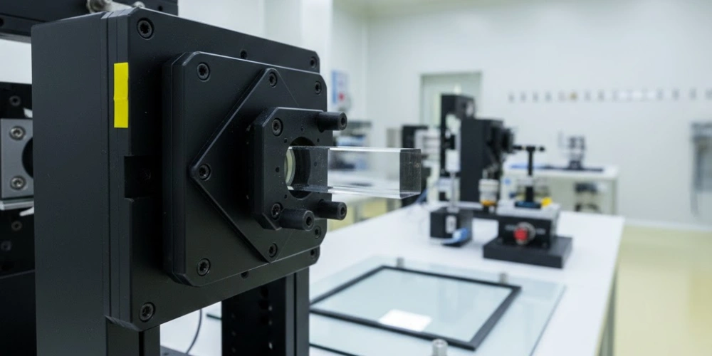
Application Domains Suited for Square Fused Silica Rods
Following the full characterization of optical, dimensional, and thermal behavior, the application fit for each geometry becomes directly traceable to its measurable performance attributes.
The application suitability of square fused silica rods is determined not by convention but by the convergence of three performance demands that only flat-wall TIR geometry can simultaneously satisfy: top-hat intensity output, UV-band transparency, and sub-millimeter edge definition at the output aperture. These three requirements co-occur in a well-defined set of industrial and scientific optical systems, and within these systems, square rod geometry is functionally irreplaceable.
Excimer Laser Annealing in Flat Panel Display Fabrication
Excimer laser annealing (ELA) for low-temperature polysilicon (LTPS) crystallization in OLED and LCD flat panel display production is the highest-volume industrial application for square fused silica rod homogenizers. The process requires a line-shaped beam — typically 400–700 mm long and 0.3–0.5 mm wide at the substrate — delivering uniform fluence within ±3% P-V across the full line length to ensure consistent grain size across the panel area.
Square fused silica rods in ELA systems typically measure 1 mm × 1 mm to 3 mm × 3 mm in cross-section, with lengths of 60–120 mm (aspect ratios of 40:1 to 80:1 at the narrow cross-section dimension), operating at 308 nm (XeCl) or 248 nm (KrF) excimer wavelengths. The high OH-content (> 1000 ppm) synthetic fused silica grade used in these rods provides DUV transmission stability under cumulative fluences exceeding 10⁹ J/cm² over the rod service lifetime. Output uniformity from optimized square rod homogenizers in ELA systems is routinely verified at ±2% to ±3% P-V across the line beam, meeting the crystallization uniformity threshold for Gen-8 panel (2,200 mm × 2,500 mm) production at throughputs of 60–90 substrates per hour.
The square rod's output aperture geometry directly defines the aspect ratio of the line beam projected onto the substrate through the downstream cylindrical optics, making cross-section dimension a system-level design parameter rather than a component-level detail.
Laser Welding and Material Processing with Homogenized Beams
In laser welding, laser cutting, and laser marking applications, the transition from a Gaussian to a Top-hat beam profile produced by a square fused silica rod homogenizer delivers measurable process improvements in material processing quality. A Gaussian beam concentrates peak intensity at its center, creating a non-uniform energy deposition profile that produces variable melt depth and inconsistent heat-affected zone (HAZ) width across the weld spot. A Top-hat beam distributes energy uniformly across the spot area, producing a consistent melt depth and a well-defined HAZ boundary.
For laser welding of thin metal sheets (0.1–0.5 mm thickness) with Top-hat beam profiles from square rod homogenizers, weld bead width uniformity improves from ±15% to ±20% (Gaussian) to ±3% to ±5% (Top-hat), and the incidence of spattering events — caused by localized peak-intensity boiling — decreases by a factor of 3–5×. Rod cross-sections for welding applications typically range from 3 mm × 3 mm to 8 mm × 8 mm, with aspect ratios of 10:1 to 15:1, optimized for 1064 nm or 1030 nm Yb:YAG laser wavelengths. AR coatings at the rod end faces (R < 0.2% per surface) are standard to maintain total transmission above 95% at these wavelengths.
The square output aperture of the rod maps directly to a square or rectangular spot at the work surface through the projection optics, enabling precise control of heat-affected zone geometry — a requirement in electronics PCB drilling and precision microstructuring applications.
UV Lithography and Semiconductor Inspection Systems
Deep UV lithography illuminators and semiconductor wafer inspection systems impose the strictest beam uniformity requirements of any commercial optical system — typically ±1% to ±2% P-V across the illumination field — and square fused silica rods are embedded within their illumination trains as critical uniformity-conditioning elements.
In 193 nm ArF immersion lithography systems, the illumination uniformity specification at the reticle plane directly governs critical dimension (CD) uniformity across the wafer — a 1% non-uniformity in illumination translates to approximately 0.3–0.5 nm CD variation at 7 nm technology node geometries, which exceeds the process control budget. Square fused silica rods used in these systems are fabricated from radiation-hardened grade fused silica with OH content > 1000 ppm and metal impurity levels below 1 ppm to minimize color center formation under ArF irradiation. Surface specifications of 10-5 scratch-dig on end faces and Ra < 0.3 nm on sidewalls are standard for lithography-grade rods. Inspection systems operating at 193 nm or 266 nm similarly require square rod homogenizers to deliver uniform illumination across silicon wafer surfaces for defect detection at sub-10 nm sensitivity levels.
Square Rod Application Parameters
| Application | Wavelength (nm) | Rod Cross-Section (mm) | Aspect Ratio | Required Uniformity (P-V) |
|---|---|---|---|---|
| ELA / LTPS display annealing | 308 / 248 | 1×1 to 3×3 | 40:1 to 80:1 | ±2% to ±3% |
| Laser welding / material processing | 1064 / 1030 | 3×3 to 8×8 | 10:1 to 15:1 | ±3% to ±5% |
| ArF lithography illumination | 193 | 1×1 to 2×2 | 30:1 to 60:1 | ±1% to ±2% |
| Wafer inspection illumination | 193 / 266 | 1×1 to 3×3 | 20:1 to 40:1 | ±2% to ±3% |
| Laser marking / scribing | 355 / 532 | 2×2 to 5×5 | 10:1 to 20:1 | ±5% to ±8% |
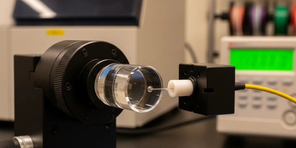
Application Domains Suited for Round Fused Silica Rods
Round fused silica rods occupy a distinct and well-defined application niche where their rotational symmetry and curved-sidewall properties provide functional advantages that square geometry cannot replicate.
Fiber optic coupling is the most direct application of round rod geometry. Round rods with diameters matched to standard fiber cladding dimensions (125 μm to 1000 μm) serve as mode-matching elements, depolarizers, and beam expanders within all-silica fiber optical systems, maintaining full rotational symmetry compatibility with the fiber's circular waveguide mode structure. Coupling efficiencies above 85% between single-mode fibers and round rods are routinely achieved in NA-matched configurations.
Evanescent wave sensing exploits the circumferentially continuous evanescent field of the round rod sidewall to interrogate analyte layers over the full rod circumference simultaneously. Round fused silica sensing rods at 633 nm achieve refractive index sensitivities of 10⁻⁷ RIU, enabling detection of protein binding, DNA hybridization, and chemical concentration changes in microfluidic environments where the circular rod geometry integrates naturally with cylindrical flow cell housings.
Polarimetric and interferometric beam delivery benefits from the radially symmetric stress birefringence distribution of round rods, which produces zero net polarization rotation in symmetric illumination conditions — a property exploited in reference arm delivery of laser interferometers and in wavefront sensing systems where polarization state integrity is required over long propagation paths.
High-temperature environment applications — including pyrometry, combustion diagnostics, and industrial process monitoring through high-temperature process chambers — utilize round fused silica rods as light-pipe conduits. The circular cross-section's rotationally invariant collection solid angle ensures isotropic coupling to omnidirectional thermal emission sources, with rod diameters from 3 mm to 20 mm and lengths up to 500 mm used in industrial pyrometer systems operating continuously at ambient temperatures up to 300°C with rod-tip temperatures reaching 800°C.
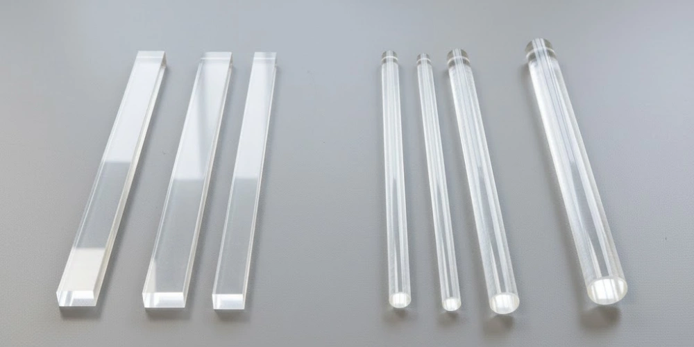
A Comparative Summary of Square and Round Fused Silica Rods
All preceding analysis converges into a clear differentiation matrix that enables direct, parameter-specific comparison between the two geometries across the full range of performance dimensions addressed in this article.
The fundamental distinction is not one of quality — neither geometry is inherently superior — but of functional alignment between geometric optical behavior and application requirement. Square fused silica rods deliver deterministic beam homogenization, flat-top intensity output, and rectangular aperture definition at the cost of increased dimensional complexity and corner thermal sensitivity. Round fused silica rods deliver rotational symmetry preservation, simplified dimensional control, and circumferential evanescent field continuity at the cost of inherent beam non-uniformity and incompatibility with flat-top intensity requirements.
Every system specification decision should trace back to the optical output requirement: if uniform intensity distribution across a defined rectangular aperture is the primary criterion, square geometry is the only physically valid selection. If rotationally symmetric beam preservation, fiber mode matching, or evanescent field sensing is the primary criterion, round geometry is the appropriate choice.
Full Comparative Summary
| Performance Dimension | Square Fused Silica Rods | Round Fused Silica Rods |
|---|---|---|
| TIR consistency | High — fixed surface normal | Variable — rotating surface normal |
| Output beam uniformity (P-V) | ±2% to ±5% (optimized) | 20–60% (geometry-limited) |
| Flat-top output capability | Yes — deterministic | No — geometry-limited |
| Rotationally symmetric output | No — rectangular aperture | Yes — circular aperture |
| Sidewall tolerance complexity | High (flatness, parallelism, perpendicularity) | Low (cylindricity, diameter) |
| Corner thermal stress concentration | Present (2–4 MPa at 10 W/cm²) | Absent |
| Stress birefringence under load | Asymmetric (corner-dominated) | Symmetric (radial) |
| Fiber coupling compatibility | Low — mode mismatch | High — circular symmetry |
| Evanescent field continuity | Discrete (4 zones) | Continuous (360°) |
| Primary wavelength range | 160–2500 nm (shared) | 160–2500 nm (shared) |
| Key applications | ELA, lithography, laser welding, UV inspection | Fiber coupling, sensing, polarimetry, pyrometry |
| Aspect ratio for optimal uniformity | 12:1 to 20:1 | Not applicable for uniformity |
| AR coating benefit | +2% to +3% P-V uniformity gain | Transmission improvement only |
| Dimensional verification complexity | High (5+ parameters) | Low (2–3 parameters) |
Conclusion
Square and round fused silica rods are not interchangeable components — they are geometrically distinct optical elements whose propagation physics, output characteristics, and tolerance architectures diverge at the most fundamental level. Square fused silica rods achieve their functional primacy in beam homogenization through the deterministic TIR geometry of four planar sidewalls, producing flat-top intensity outputs within ±2% to ±5% P-V that are unattainable by any round rod configuration. Round fused silica rods maintain their indispensable role in fiber coupling, evanescent sensing, and polarimetric systems through the rotational symmetry properties that flat-wall geometry structurally cannot provide. System designers specifying optical rod components should apply geometry selection as the primary decision axis, treating all downstream parameters — aspect ratio, surface quality, AR coating specification, and mounting configuration — as consequential variables that must be optimized within the geometry already determined by the application's optical output requirement.
FAQ
What is the main optical difference between square fused silica rods and round fused silica rods?
The primary optical difference is in internal ray propagation geometry. Square fused silica rods have four planar sidewalls with fixed surface normals, producing consistent total internal reflection paths that redistribute optical energy into a uniform Top-hat intensity profile. Round rods have a continuously curving sidewall with a rotating surface normal, producing spatially variant reflection paths that cannot generate a flat-top output distribution regardless of rod length.
Why are square fused silica rods used in excimer laser annealing systems?
Excimer laser annealing for LTPS crystallization requires a line beam with intensity uniformity within ±3% P-V across the full line length. Only square rod homogenizers can achieve this specification at 248 nm and 308 nm excimer wavelengths, combining the flat-top beam shaping capability of planar TIR geometry with the deep UV transparency of high-OH synthetic fused silica. Round rods cannot meet the uniformity requirement of ELA systems.
What aspect ratio should be used for square fused silica rod beam homogenizers?
For most laser homogenization applications requiring ±3% to ±5% P-V output uniformity with total transmission above 90%, an aspect ratio (length divided by side dimension) of 12:1 to 20:1 is the optimal range for AR-coated square fused silica rods. Ratios below 12:1 produce insufficient ray redistribution; ratios above 25:1 add propagation losses without proportional uniformity improvement.
Can round fused silica rods be used instead of square rods for beam homogenization?
Round fused silica rods are not suitable substitutes for square rods in beam homogenization applications. The best achievable output uniformity from a round rod — even at aspect ratios of 30:1 — is approximately 20–30% P-V, compared to the 2–5% P-V achievable with square rods. This ten-fold performance gap reflects a fundamental geometric limitation, not a manufacturing deficiency, and cannot be overcome by extending rod length or improving surface quality.
References:
-
A Gaussian beam is the fundamental transverse mode of laser radiation, characterized by a bell-shaped intensity profile that is the standard input condition for beam homogenization systems. ↩
-
ISO 11146 is the international standard defining measurement methods for laser beam widths, divergence angles, and beam propagation ratios used in uniformity characterization. ↩
-
Fatigue crack initiation is the process by which cyclic mechanical stress at a material surface flaw nucleates a propagating crack over repeated load cycles, relevant to pulsed laser operation of optical rods with surface defects. ↩