Premature failure and compromised analytical results are the measurable consequences of inadequate labware maintenance. A component-specific cleaning protocol preserves the structural and chemical integrity of every fused silica part in active service.
Quartz glass laboratory components are produced in a broad spectrum of physical forms, each carrying distinct contamination profiles, thermal histories, and surface sensitivities. Cleaning and maintenance requirements differ substantially across crucibles, tubing, optical windows, boats, and fittings — and a generalized protocol serves none of them adequately.
Maintenance discipline in fused silica labware is not reducible to surface cleanliness alone. The optical transmission, thermal stability, and chemical inertness that justify the use of fused silica in precision laboratory environments are all degraded by deferred or imprecise maintenance intervention.
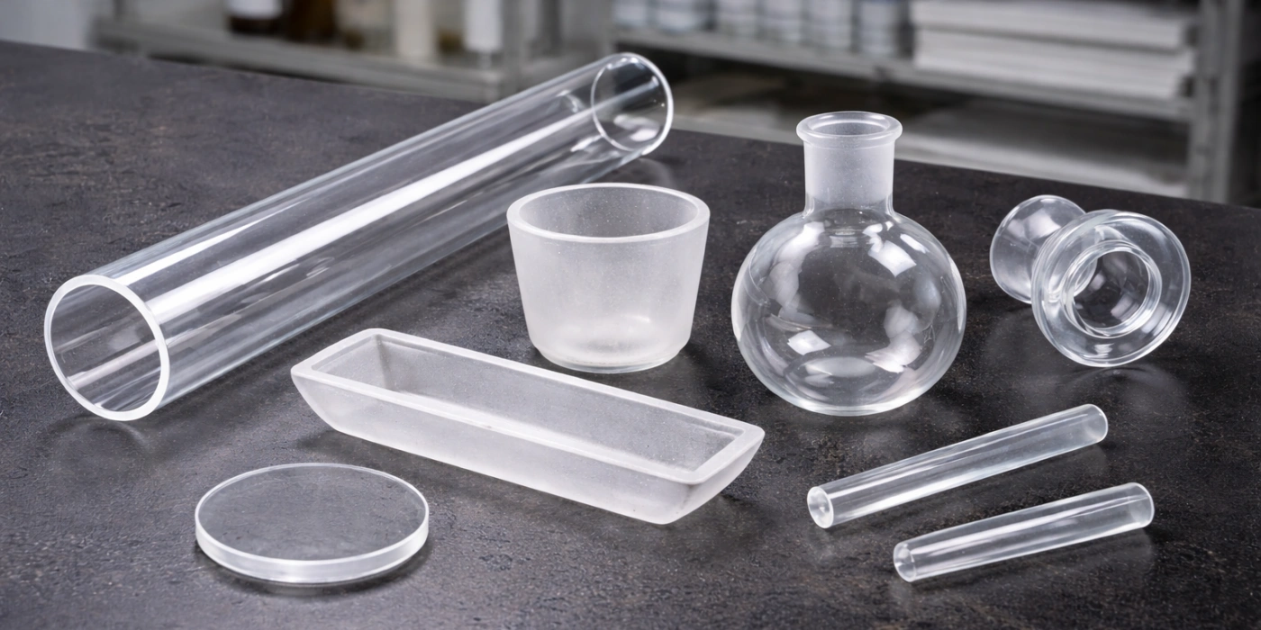
The Spectrum of Quartz Glass Forms Used in Laboratory Settings
Fused silica appears across laboratory infrastructure in a broader range of physical forms than many practitioners initially appreciate. Each form carries a distinct functional role, and understanding these forms is the prerequisite for applying any cleaning or maintenance strategy with precision.
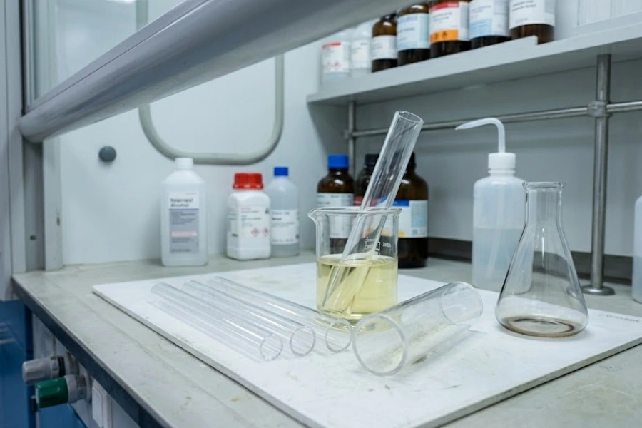
Quartz Tubing is among the most universally deployed forms, used in tube furnaces, CVD reactors, gas delivery lines, and photochemical flow systems. Available in outer diameters ranging from 2 mm to over 200 mm, tubing is exposed to process gases, reactive vapors, and thermal cycling that deposit both inorganic and organic residues across its inner bore surface.
Quartz Flasks and Reaction Vessels serve photochemical synthesis, UV-initiated reactions, and acid digestion processes. Their enclosed geometry creates retention zones where residues accumulate at the base and along interior shoulders, making complete solvent exchange during cleaning particularly challenging.
بوتقات الكوارتز operate at the highest thermal loads of any component type, routinely sustaining temperatures between 1,000 °C and 1,700 °C in metal melting, ceramic sintering, and ashing applications. At these extremes, surface devitrification — the partial crystallization of amorphous fused silica — becomes the primary degradation mechanism.
Quartz Boats and Trays are widely used in semiconductor diffusion furnaces, calcination workflows, and catalyst evaluation setups. Their flat geometry maximizes sample exposure area, but also maximizes the surface area susceptible to contamination from molten materials and oxide formation during thermal cycling.
قضبان الكوارتز and Stirring Elements function as mechanical agitators in corrosive acid baths and high-temperature mixing environments. Their surface-to-volume ratio is high, meaning even thin contamination films represent a proportionally significant chemical interference source. Quartz rods used in semiconductor wet processing baths, for example, accumulate hydrofluoric acid treatment residues and photoresist fragments across their full surface length, necessitating cleaning protocols that match the full chemical diversity of the bath environments they serve.
Quartz Sight Glasses and Optical Windows serve as optically transparent interfaces in reaction chambers, UV irradiation systems, plasma reactors, and spectroscopic flow cells. Operating in the UV through near-IR transmission range, these components are uniquely sensitive — any surface contamination, micro-scratching, or thin-film deposition directly degrades the optical performance metrics they are installed to deliver.
Quartz Flanges and Fittings connect process chambers, furnace tubes, and gas manifolds. Sealing surfaces on flanges must be maintained to exacting flatness tolerances to prevent vacuum leaks or gas bypass, meaning cleaning protocols must avoid any mechanical action that could alter surface geometry. In high-vacuum applications, even a single circular scratch across a flange sealing face can represent a virtual leak path with conductance sufficient to prevent the system from reaching target base pressure — making the preservation of sealing surface integrity a performance-critical maintenance objective in its own right.
The diversity of these component forms underscores a central principle: a single generalized cleaning protocol cannot serve all quartz glass laboratory components adequately. The sections that follow address each major component category with the specificity their distinct functional requirements demand.
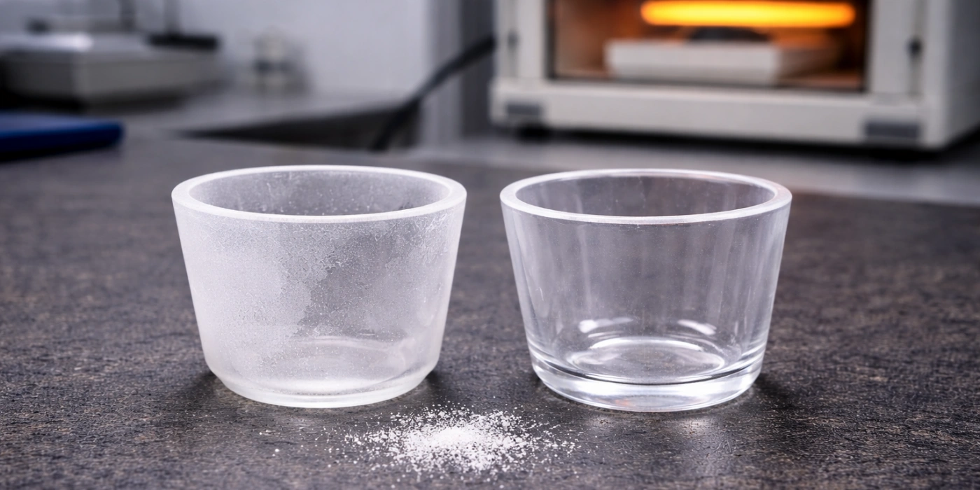
Why Contamination and Structural Degradation Threaten Quartz Components
Across all component types, four primary degradation mechanisms drive the need for systematic cleaning and maintenance. Understanding these mechanisms at a material level enables practitioners to select interventions that address root causes rather than symptoms alone.
-
Devitrification — the crystallization threat to fused silica. When fused silica is held above approximately 1,050 °C in the presence of alkali metal contaminants — particularly sodium and potassium ions from fingerprints, airborne particles, or process residues — the amorphous silica network begins to reorganize into crystalline cristobalite. This phase transition is irreversible and propagates outward from nucleation sites on the surface. Devitrified zones exhibit a characteristic milky, opaque appearance; mechanically, they represent stress concentration points with substantially reduced fracture toughness, increasing the risk of catastrophic failure during subsequent thermal cycling. Research indicates that even sodium ion concentrations as low as 0.1 ppm on the surface can accelerate devitrification onset by more than 200 °C below the theoretical crystallization temperature of pure fused silica. Once initiated, the crystallization front advances at a rate of approximately 0.5–2 µm per hour at 1,200 °C, meaning that a component exposed to a single 8-hour furnace run at high temperature in a sodium-contaminated state can accumulate a devitrification layer 4–16 µm deep — thick enough to be structurally consequential and to require chemical remediation before further service.
-
Metallic ion contamination and its optical consequences. Transition metal ions — iron, chromium, nickel, and copper — introduced through contact with metal tools, contaminated process gases, or reaction byproducts absorb strongly in the UV and visible spectral regions. Iron contamination at concentrations above 10 ppm in the silica matrix produces measurable absorption at 380 nm, directly compromising UV transmission performance. For optical windows and spectroscopic cells, this renders the component functionally obsolete long before any structural failure occurs.
-
Thermal stress accumulation across repeated heating cycles. Fused silica possesses an exceptionally low coefficient of thermal expansion (approximately 0.55 × 10⁻⁶/°C), which provides inherent resistance to thermal shock. Nevertheless, repeated rapid thermal cycling induces cumulative micro-stress at surface defects and wall thickness variations. Over time, these micro-stresses coalesce into propagating micro-cracks, particularly at rim edges, bore entrances, and wall junctions where geometric stress concentration is highest.
-
Surface hydroxyl group degradation under sustained UV exposure. Silanol (Si-OH) groups on the fused silica surface are reactive sites that can form hydrogen bonds with moisture and organic molecules, promoting surface contamination adhesion. Prolonged exposure to deep UV radiation below 200 nm causes photolytic conversion of silanol groups and the generation of color centers — point defects that increase UV absorption and reduce transmission uniformity across the aperture.
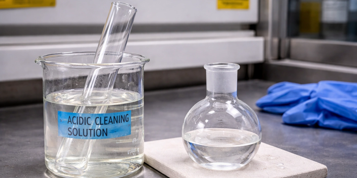
Cleaning Protocols for Quartz Tubing and Reaction Vessels
Precise cleaning methodology for quartz glass laboratory components in tubular and vessel form depends entirely on the nature of the contamination present, the geometry of the component, and the sensitivity of subsequent analytical operations. Each contamination type demands a targeted chemical intervention; applying a generalized protocol risks either insufficient decontamination or unnecessary surface etching that accelerates wear.
Removing Organic Residues with Solvent and Alkaline Washes
Organic contamination — comprising hydrocarbon films, polymer deposits, silicone grease residues, and biological matrices — represents the most frequently encountered fouling class in quartz tubing used in flow chemistry, photochemical reactors, and gas delivery systems.
The most effective initial intervention is a sequential solvent rinse: acetone followed by isopropanol (IPA)1, each applied in a minimum three-pass flush through the bore. Acetone dissolves non-polar hydrocarbon films and grease residues with high efficiency, while IPA subsequently removes the acetone film and polar organic species in a single complementary step. This two-solvent sequence reduces total organic carbon (TOC) loading on the surface by approximately 85–90% before any aqueous treatment begins, significantly reducing the chemical demand on subsequent alkaline or acid wash stages.
For carbonized or polymerized deposits that resist solvent flushing, a 5–10% sodium hydroxide (NaOH) solution applied at 60–80 °C for 30–60 minutes provides effective saponification of ester linkages and hydrolysis of silicone-based residues. Following alkaline treatment, a minimum of five ultrapure water rinses with resistivity ≥18.2 MΩ·cm is mandatory to remove all sodium ions from the silica surface before the component is returned to high-temperature service, as residual alkali metal ions are direct devitrification initiators.
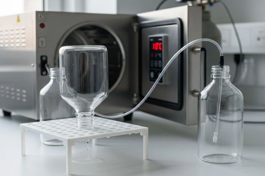
A final drying step in a clean-air oven at 120 °C for 60 minutes eliminates adsorbed moisture from the bore surface, restoring the surface condition required for reliable high-temperature operation.
Acid-Based Cleaning for Metallic Deposits and Oxide Layers
Metallic contamination — including iron oxide scales, calcium carbonate deposits, and transition metal residues from process reagents — requires acid-based protocols that dissolve inorganic deposits without attacking the fused silica matrix itself.
Hydrochloric acid (HCl) at 10–20% concentration is the first-line reagent for iron oxides, calcium deposits, and most divalent metal hydroxides, operating through straightforward proton-driven dissolution. Immersion or recirculation at ambient temperature for 30–60 minutes is sufficient for moderate deposit loads; heavily scaled surfaces may require 2–4 hours at 40–50 °C with periodic agitation. Nitric acid (HNO₃) at 10–30% concentration complements HCl by oxidizing metallic deposits that are resistant to proton-only dissolution — particularly chromium oxide and nickel residues from stainless steel process equipment. For extreme contamination involving noble metal deposits (platinum, gold, or palladium catalyst residues), aqua regia — a 3:1 volumetric mixture of HCl and HNO₃ — is applicable, but contact time must be rigorously controlled to under 15 minutes at ambient temperature to prevent measurable etching of the silica surface itself.
Following any acid treatment, a minimum of seven ultrapure water rinses is required, and a final dilute ammonia rinse (0.1% NH₄OH) can be employed to neutralize any residual acid retained in micropores or surface recesses before the terminal water wash sequence.
The choice between HCl and HNO₃ as the primary acid is not arbitrary — it depends on the oxidation state of the metallic deposit. Divalent metal oxides such as FeO, CaO, and MgO respond rapidly to HCl through proton-driven dissolution, while higher oxidation state species including Fe₂O₃, Cr₂O₃, and NiO require the oxidizing environment that HNO₃ provides to convert the metal ion into a soluble form. When deposit composition is uncertain, a sequential treatment beginning with 15% HCl followed by 20% HNO₃ covers the full redox spectrum and achieves complete metallic deposit removal within a combined contact time of 60–90 minutes at 40 °C, minimizing unnecessary acid exposure of the silica surface by targeting the correct dissolution mechanism for each deposit layer in sequence.
HF Etching for Surface Restoration of Fused Quartz Tubing
Hydrofluoric acid (HF) etching is a surface restoration technique applied when quartz tubing surfaces exhibit devitrification nucleation, embedded metallic contamination that resists acid dissolution, or surface roughening from prior aggressive treatments that has increased contamination adhesion.
HF reacts with fused silica through the formation of silicon tetrafluoride (SiF₄) and hexafluorosilicic acid (H₂SiF₆), progressively dissolving the silica surface layer at a controlled rate. At 1–5% HF concentration, the etch rate on fused silica is approximately 0.1–0.3 µm per minute at ambient temperature, enabling controlled removal of surface-resident contamination without compromising wall thickness on standard-gauge tubing. Contact time should not exceed 5 minutes at 5% concentration; after etching, a thorough rinse sequence of at minimum eight ultrapure water flushes is mandatory, followed by a 1% ammonia neutralization wash.
HF etching is contraindicated for thin-walled tubing with wall thickness below 1.5 mm, where cumulative etch depth represents a structurally significant fraction of total wall thickness. TOQUARTZ quartz tubing is manufactured with inner bore surface roughness (Ra) values consistently below 0.4 µm, a surface finish quality that substantially reduces the adhesion of both organic and inorganic contaminants to the bore wall. In laboratory evaluations, this surface finish specification reduces the frequency at which HF etching becomes necessary by an estimated 40–60% compared to tubing produced to standard commercial surface finish tolerances, preserving wall thickness over the component's operational lifespan.
Ultrasonic Cleaning Applications and Their Limitations
Ultrasonic cleaning — operating through acoustic cavitation — dislodges surface-bound particulates, loosely adhered films, and contaminants residing in surface microfeatures that are inaccessible to direct chemical flushing. Operating frequencies of 25–40 kHz are effective for larger particulate removal, while 80–130 kHz frequencies produce finer cavitation bubbles better suited to cleaning microstructured surfaces and bore interiors.
The critical limitation of ultrasonic cleaning for quartz tubing is cavitation-induced micro-stress, particularly in thin-walled sections and at rim edges where geometric stress concentration amplifies the cyclic pressure waves generated during cavitation collapse. Wall thickness uniformity directly governs the safety envelope: tubing with wall thickness variations exceeding ±0.3 mm creates localized resonance zones where cavitation stress is disproportionately concentrated, increasing micro-crack propagation risk. TOQUARTZ quartz tubing maintains wall thickness uniformity within ±0.15 mm across standard bore sizes — a tolerance specification that effectively doubles the safe ultrasonic exposure window compared to tubing manufactured to ±0.3 mm tolerances, enabling confident use of ultrasonic cleaning as a routine maintenance step rather than an occasional high-risk intervention.
Comparative Cleaning Method Performance for Quartz Tubing
| Contamination Type | Primary Method | Secondary Method | Contact Time | درجة الحرارة (درجة مئوية) | Effectiveness Rating |
|---|---|---|---|---|---|
| Light organic films | Acetone + IPA flush | - | 3-pass flush | المحيط | ★★★★★ |
| Polymerized organics | NaOH 5–10% | IPA rinse | 30–60 min | 60-80 | ★★★★☆ |
| Iron oxide / carbonate | HCl 10–20% | Ultrapure H₂O rinse | 30–120 min | Ambient–50 | ★★★★★ |
| Noble metal deposits | Aqua regia | HNO₃ rinse | ≤15 min | المحيط | ★★★★☆ |
| Surface devitrification | HF 1–5% | NH₄OH neutralization | ≤5 min | المحيط | ★★★☆☆ |
| Particulate deposits | Ultrasonic 25–40 kHz | Ultrapure H₂O rinse | 10–20 min | 40–50 | ★★★★☆ |
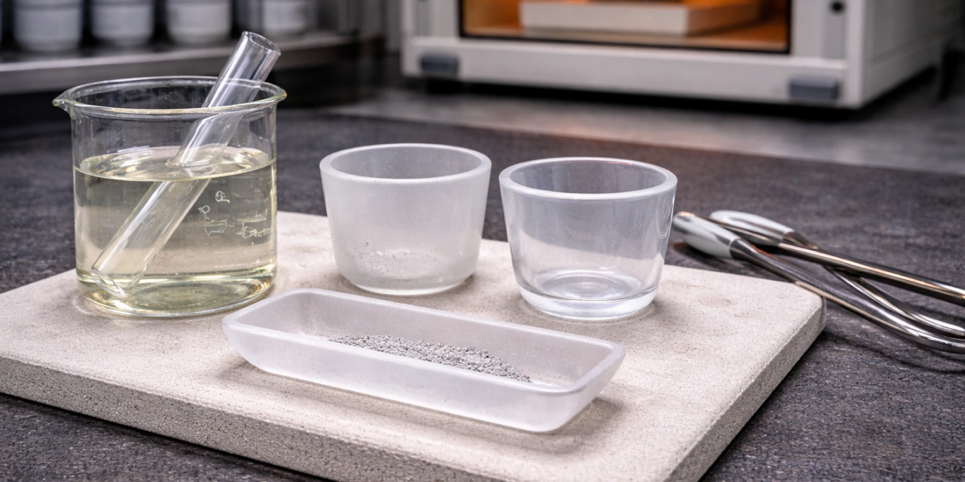
Maintenance and Cleaning Specifics for Quartz Crucibles and Boats
Among the most thermally demanding of all quartz glass laboratory components, crucibles and boats operate in conditions that render the cleaning challenges encountered in tubing and vessels relatively mild by comparison. The combination of sustained extreme temperatures, direct contact with reactive molten materials, and repeated thermal cycling produces a contamination and degradation profile that requires a substantially different maintenance approach.
Addressing Devitrification Deposits on Crucible Surfaces
Devitrification on crucible surfaces manifests as a white, opaque crystalline layer — typically cristobalite — that forms preferentially at the outer rim, base exterior, and any surface region that has sustained repeated contact with alkali-containing materials or atmospheric moisture at elevated temperatures.
The standard remediation protocol for surface devitrification employs a mixed HF/HCl solution: 2–5% HF combined with 10–15% HCl, applied by immersion at ambient temperature for 3–8 minutes depending on devitrification layer thickness. The HF component attacks the crystalline silica directly through Si-F bond formation, while the HCl component dissolves associated metallic impurities that co-deposited during crystallization. Following treatment, a minimum of eight ultrapure water rinses is required, with pH verification of the final rinse water confirming complete acid removal before the crucible is returned to service. For crucibles with devitrification penetrating more than 0.3 mm into the wall thickness — as estimated by the opacity gradient visible under transmitted light — mechanical surface abrasion with a fine-grit alumina slurry (600–800 mesh) can supplement chemical treatment, though this approach removes material permanently and must be followed by a confirmatory wall thickness measurement.
TOQUARTZ crucibles are produced with a surface densification treatment that raises the effective devitrification onset temperature by approximately 80–120 °C above untreated fused silica, achieved through controlled surface hydroxyl group reduction during final processing. In practical terms, crucibles subjected to repeated service at 1,200 °C require devitrification remediation approximately every 18–24 months under standard laboratory service cycles, compared to 8–12 months for conventionally finished crucibles — a maintenance interval extension that meaningfully reduces the cumulative chemical treatment burden and associated handling risk over the component's service life.
Eliminating Molten Metal and Slag Residue from Quartz Boats
Quartz boats used in metal annealing, semiconductor diffusion, and catalyst calcination accumulate surface residues that span the full spectrum from loose oxide powders to firmly bonded metallic films and vitrified slag layers.
Loose oxide deposits — including iron oxide, aluminum oxide, and calcium oxide — respond effectively to 10–20% HCl at 40–60 °C, with immersion times of 30–90 minutes depending on deposit density. Metallic deposits in the native metal state, rather than oxide form, require oxidizing acid treatment: HNO₃ at 20–30% concentration oxidizes the surface of metallic deposits to their soluble ionic forms, after which HCl can complete dissolution. For tenacious slag residues formed by vitrification of mixed oxide systems at high temperatures, the most reliable approach is a sequential treatment: initial mechanical loosening with a ceramic spatula (never metallic tools, which introduce contamination), followed by aqua regia immersion for 10–15 minutes, followed by extended ultrapure water rinsing over a minimum 1-hour period with multiple water changes.
High-pressure deionized water rinsing at 2–4 bar serves as a highly effective supplementary step between acid treatments, physically dislodging loosened deposit fragments from the flat tray surface before they can re-adhere during the transition between acid bath stages. This step reduces the total acid exposure time required and preserves the surface finish of the boat floor.
Thermal Annealing as a Maintenance Step for Stress Relief
Repeated rapid thermal cycling — characteristic of diffusion furnace boats and calcination trays — induces cumulative residual stress within the fused silica body that is not visible on the surface but progressively increases fracture susceptibility over the component's service life.
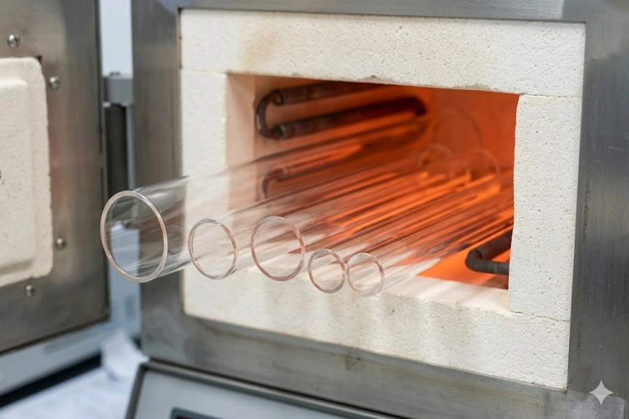
Thermal annealing at 1,000–1,200 °C with carefully controlled heating and cooling rates provides structural stress relief by allowing the fused silica network to relax toward its equilibrium configuration at elevated temperature. The critical parameters are the heating rate (recommended: ≤3 °C/min below 800 °C, ≤5 °C/min from 800–1,200 °C) and the cooling rate (mandatory: ≤2 °C/min through the 1,000–700 °C range, where the silica network is most susceptible to re-stressing). Soaking at maximum temperature for 60–120 minutes is required for full stress relaxation across the full wall thickness of standard boat geometries. Residual stress prior to annealing can be qualitatively assessed by placing the boat under a polarized light source: stress birefringence manifests as color fringes at formerly stressed zones, providing a visual confirmation that annealing treatment has been effective when fringes diminish or disappear post-treatment.
TOQUARTZ quartz boats and crucibles are characterized by thermal uniformity specifications of ±15 °C across the component body at service temperature, compared to ±30–50 °C variation commonly observed in conventionally manufactured quartz ware. This thermal uniformity specification means that during annealing treatments, the temperature gradient across the component body is sufficiently small to prevent differential expansion from inducing new stress during the very maintenance procedure intended to relieve existing stress — a technically meaningful distinction that directly improves the reliability of annealing as a maintenance intervention.
Cleaning and Maintenance Protocol Summary for Crucibles and Boats
| الإصدار | العامل الكيميائي | التركيز | درجة الحرارة (درجة مئوية) | Contact Time | Rinse Cycles |
|---|---|---|---|---|---|
| Surface devitrification | HF + HCl mixed | 2–5% HF / 10–15% HCl | المحيط | 3–8 min | ≥8 ultrapure H₂O |
| Iron / calcium oxide deposits | حمض الهيدروكلوريك | 10–20% | 40-60 | 30–90 min | ≥6 ultrapure H₂O |
| Metallic residues (native metal) | HNO₃ then HCl | 20–30% / 10–20% | المحيط | 20–60 min | ≥8 ultrapure H₂O |
| Vitrified slag | Aqua regia | 3:1 HCl:HNO₃ | المحيط | 10–15 min | ≥10 ultrapure H₂O |
| Residual stress accumulation | Thermal annealing | غير متاح | 1,000-1,200 | 60–120 min soak | غير متاح |
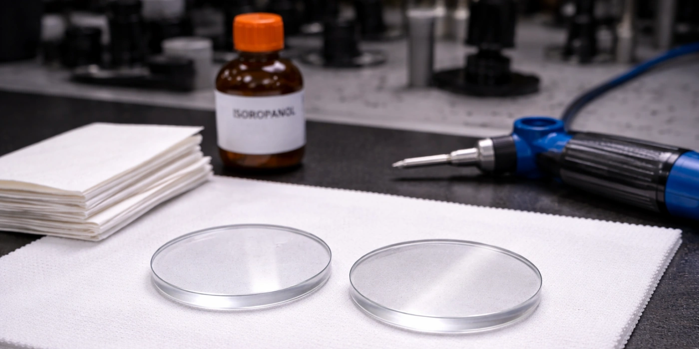
Optical Components — Cleaning Sight Glasses and Quartz Windows
Of all quartz glass laboratory components, optical windows and sight glasses impose the most stringent cleaning constraints — not because they are chemically more fragile, but because their functional criterion is optical performance rather than chemical purity or structural integrity alone. A mechanically intact window that carries a 5 nm RMS surface roughness from an abrasive cleaning event is, for UV spectroscopic applications, as compromised as a fractured one.
Surface Cleaning Without Compromising Optical Transmission
The fundamental principle governing optical surface cleaning is the absolute avoidance of any mechanical action that introduces or propagates surface micro-scratches above the component's specified scratch-dig rating.
First-Contact polymer cleaning films — a removable elastomeric formulation originally developed for astronomical mirror surfaces — represent the current gold standard for particle removal from optical quartz surfaces. Applied in liquid form and peeled away after curing, First-Contact lifts particulate contamination and loose organic films from the surface without any frictional contact, achieving surface cleanliness levels verifiable at scratch-dig 20-10 or better on surfaces previously rated at 40-20. Where First-Contact is not available, the only acceptable alternative contact method is a folded optical-grade lens tissue dampened with a 70:30 IPA:ultrapure water mixture, applied in a single radial stroke from center to edge — never in circular or reciprocating motions that concentrate abrasive particulates at a single surface point. Nitrogen gas blow-off at 1–2 bar using a filtered, oil-free source should precede any contact cleaning step to remove the maximum possible loose particulate burden before mechanical contact is initiated.
All cleaning procedures for optical windows should be performed in a laminar flow2 environment or, at minimum, with the work surface isolated from ambient air currents, as airborne particulates settling onto a wetted optical surface during cleaning introduce scratches during the final drying phase.
Removing Thin-Film Deposits from UV and IR Transmission Windows
Thin-film contamination on optical quartz windows arises from three primary sources: vaporous hydrocarbon deposition from vacuum pump backstreaming, condensation of volatile process byproducts onto the cooler window surface during reactor operation, and water vapor-induced silanol layer formation under ambient storage conditions.
Low-concentration HF vapor-phase etching at 0.1–0.5% HF partial pressure is applicable for removing inorganic thin-film deposits — particularly silicon oxide and metal oxide films deposited from CVD or plasma processes — from flat optical window surfaces. Vapor-phase application is preferred over liquid immersion because it provides more uniform etch depth control across the full aperture, with etch rates of approximately 0.05–0.1 µm per minute at 25 °C providing the temporal resolution needed to stop etching before reaching the substrate surface. For hydrocarbon and organic thin films that do not respond to HF, remote oxygen plasma cleaning at 50–150 W RF power for 5–15 minutes achieves complete organic removal through oxidative fragmentation without introducing any mechanical stress or liquid-phase contamination risk. Plasma cleaning is the recommended first-line intervention for organic thin films on UV windows where transmission recovery is time-critical, as it restores transmission uniformity within 30 minutes of treatment.
Inspection Standards for Scratch and Pit Evaluation
Maintenance of optical quartz windows requires a systematic inspection protocol to confirm that cleaning procedures have not introduced new surface damage and to establish when a window has reached the end of its serviceable life.
MIL-PRF-13830B, the U.S. military optical component quality standard, provides the universally applied framework for scratch-dig assessment: the "scratch" designation quantifies the width of linear surface marks in units of 0.001 mm, while "dig" designates the diameter of point defects in units of 0.01 mm. A window rated 20-10 carries a maximum scratch width of 0.020 mm and maximum dig diameter of 0.10 mm — the standard applicable to precision UV spectroscopic and laser applications. Inspection is performed under a collimated white light source at a 45° oblique angle to the surface normal, which maximizes scatter from surface imperfections and enables visual detection of scratches below 5 µm in width. For quantitative assessment, a polarized light transmitted through the window at normal incidence reveals stress birefringence patterns around pit defects, providing supplementary information about the mechanical integrity of the subsurface region surrounding visible damage.
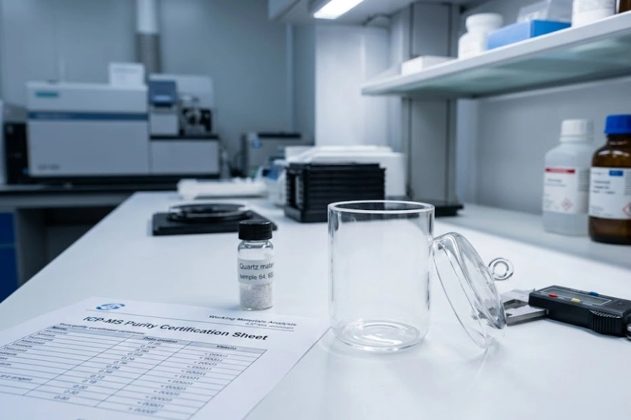
TOQUARTZ optical windows are shipped with an individual surface quality certificate specifying the measured scratch-dig rating of each unit, providing the receiving laboratory with a documented baseline against which post-cleaning and post-service inspections can be compared. This baseline documentation eliminates ambiguity in retirement decisions: when an inspection reveals surface damage exceeding the certified baseline by a defined threshold — typically one full scratch-dig grade — the maintenance record provides unambiguous evidence that the damage occurred in service rather than in manufacturing, simplifying maintenance accountability and component lifecycle management.
Optical Cleaning Method Selection by Contamination Type
| Contamination Type | الطريقة الموصى بها | Forbidden Methods | UV Transmission Recovery | مستوى المخاطرة |
|---|---|---|---|---|
| Loose particulates | N₂ blow-off + First-Contact film | Any wiping before blow-off | Full | منخفضة |
| Organic films (light) | IPA:H₂O 70:30 lens tissue wipe | Circular wiping motion | Full | منخفضة |
| Organic thin films | O₂ plasma 50–150 W, 5–15 min | Solvent immersion | Full | منخفضة |
| Inorganic thin films (CVD) | HF vapor 0.1–0.5%, ≤5 min | HF liquid immersion | Full if ≤50 nm deposit | متوسط |
| Water stains / silanol films | IPA rinse + N₂ dry | Acid immersion | Full | منخفضة |
| Surface micro-scratches | Certified polishing service | Field abrasion | Partial | N/A — professional only |
Handling, Storage and Preventive Maintenance Across All Component Types
Preventing contamination and mechanical damage before it occurs is invariably less resource-intensive than remediation after the fact. Across all quartz glass laboratory components, the following preventive practices constitute a baseline standard that substantially extends service life and reduces cleaning frequency.
-
Glove selection by component type. Nitrile gloves are the minimum requirement for all handling of fused silica components, providing an effective barrier against sodium and potassium ion transfer from skin oils — the primary environmental source of devitrification-accelerating alkali contamination. For optical windows and any component destined for high-temperature service above 1,200 °C, clean-room-grade nitrile or polyethylene gloves with verified alkali ion contamination levels below 1 µg/cm² are mandatory. Cotton gloves are explicitly contraindicated for fused silica handling, as cotton fiber fragments are highly adherent to silica surfaces and introduce metallic trace contamination from textile processing agents. Standard latex gloves are similarly unsuitable due to their sulfur content and the risk of elastomer particle transfer to the component surface.
-
Storage environment control. Fused silica components should be stored in sealed, low-humidity environments — ideally maintained at relative humidity below 40% — to minimize silanol group formation on the surface, which increases contamination adhesion during subsequent service. Storage enclosures should incorporate UV-blocking materials or be maintained in darkness, as prolonged UV exposure generates color centers in the silica network that reduce UV transmission and cannot be reversed without high-temperature annealing. Individual component storage — rather than stacked or bundled configurations — eliminates contact-induced micro-scratching during storage and retrieval. Silicone-free foam cushioning or high-purity polyethylene sheet separators are appropriate contact materials; foam products containing organosilicon compounds must be avoided as they deposit silicone films on the silica surface that are among the most difficult organic contaminants to remove completely.
-
Thermal cycling fatigue tracking. A component-level service log recording the number of thermal cycles, peak temperatures reached, and heating/cooling rates applied provides the quantitative foundation for predictive maintenance. Research on fused silica fatigue indicates that fracture probability increases measurably after approximately 500 full thermal cycles from ambient to service temperature at rates exceeding 10 °C/min, regardless of visual surface condition. Without a thermal cycle log, this predictive threshold cannot be applied; with it, components approaching the fatigue threshold can be preemptively retired or subjected to annealing treatment before failure risk escalates. A simple spreadsheet log maintained at the furnace or reactor station — recording component ID, cycle date, peak temperature, and ramp rate — provides the minimum data set required for threshold-based predictive retirement. In high-throughput laboratory environments where a single tube furnace may process 3–5 thermal cycles per day, the 500-cycle threshold can be reached within 4–6 months of installation, making active log maintenance a genuinely time-sensitive priority rather than a procedural formality.
-
Visual inspection frequency. A minimum of monthly visual inspection under a focused white light source is recommended for all high-use components, supplemented by polarized light inspection quarterly for components in optical or precision analytical service. Any newly visible opacity, surface crystallization, linear cracking, or edge chipping observed during inspection should trigger immediate removal from service and formal damage assessment before the component is returned to use.
Recognizing When Quartz Laboratory Components Require Replacement
Even with rigorous cleaning and preventive maintenance, every fused silica component reaches a state where continued service represents an unacceptable compromise of performance or safety. Establishing clear, quantitative retirement criteria removes subjective judgment from this decision and prevents both premature retirement and hazardous over-service. The absence of documented retirement criteria is among the most frequently cited contributing factors in laboratory incidents involving in-service quartz component fracture.
Devitrification severity is the primary retirement criterion for crucibles, boats, and high-temperature tubing. When devitrified surface area exceeds approximately 20% of the total component surface, or when devitrification penetrates deeper than 10% of wall thickness as measured by caliper after surface etching, the structural integrity of the component is considered compromised beyond reliable maintenance. The brittleness of cristobalite relative to amorphous fused silica means that devitrified zones serve as preferred crack initiation sites under thermal stress, and components with extensive devitrification carry a substantially elevated risk of in-service fracture.
Wall thickness reduction from cumulative HF etching, mechanical abrasion, or chemical dissolution is assessed by micrometer measurement at multiple points around the component circumference and along its length. Measurements should be taken at a minimum of eight evenly distributed circumferential positions and three longitudinal positions (near each end and at the midpoint), generating a spatial map of remaining wall thickness that identifies the thinnest cross-section. A wall thickness reduction exceeding 15% of the original specification is the standard retirement threshold for pressure-bearing or vacuum-service components; for atmospheric-service tubing and vessels, 20–25% reduction is the common limit before failure risk becomes statistically significant under thermal cycling loads. Cumulative wall thickness measurements recorded at each maintenance cycle also provide a direct empirical measurement of the component's effective consumption rate under the applied chemical cleaning regime, enabling forward projection of remaining service life.
For optical windows, measured UV transmission at the application wavelength dropping below 85% of the original certified value is the standard optical retirement criterion for deep UV applications, while visible transmission below 90% of the original specification triggers retirement for visible-range and near-IR applications. Micro-crack detection using dye penetrant testing — applying a low-viscosity fluorescent dye to the surface under vacuum and examining under UV illumination — identifies subsurface crack networks that are not visible in white light inspection and that represent imminent fracture risk under thermal or mechanical loading. Dye penetrant inspection is particularly valuable for quartz components that have experienced a thermal shock event — such as accidental cold water contact at elevated temperature — where the external surface may appear intact while internal crack networks have already propagated to a structurally critical extent.
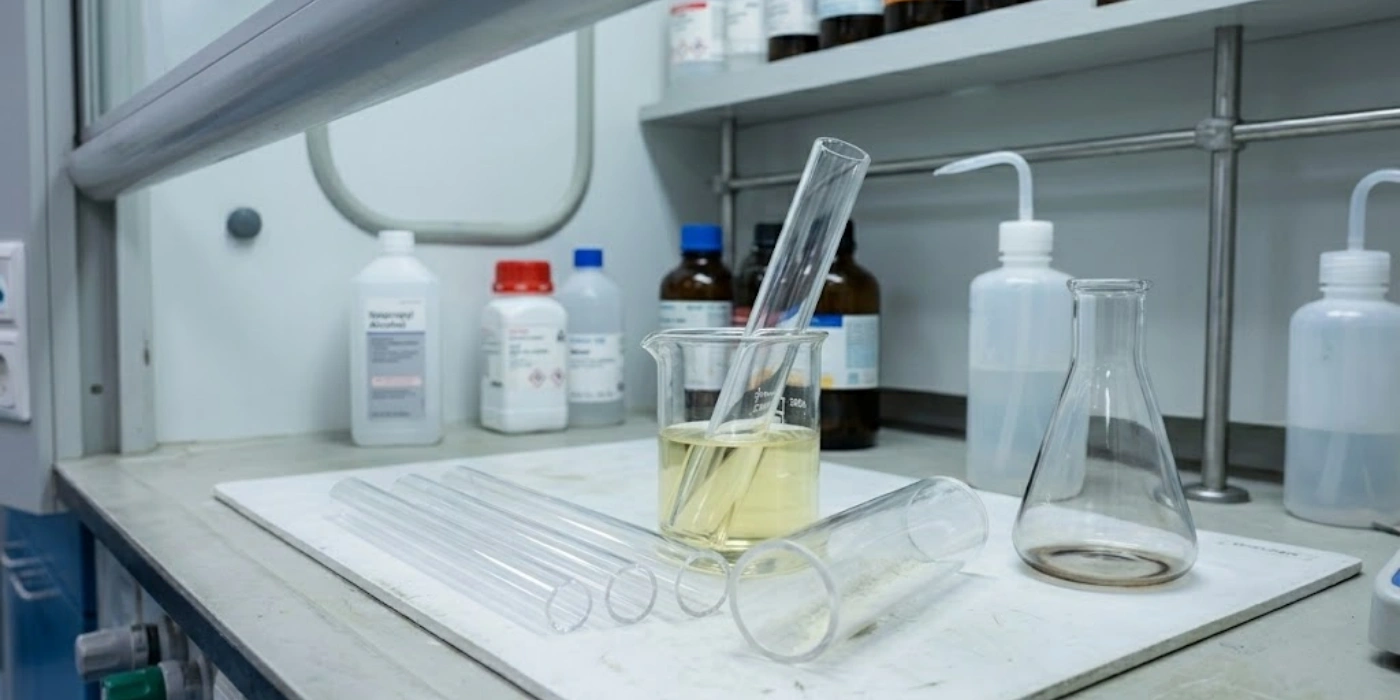
TOQUARTZ Components and Their Maintenance-Friendly Design Attributes
Built into the design and manufacturing specifications of TOQUARTZ quartz glass laboratory components is a coherent set of engineering decisions that directly reduce the labor intensity, chemical consumption, and frequency of the maintenance procedures described throughout this article. These attributes are not incidental — they represent the outcome of systematic analysis of the most common maintenance challenges encountered across the full spectrum of laboratory applications.
Surface Finish Specifications That Reduce Contamination Adhesion
The adhesion of contaminants to fused silica surfaces is governed by the real contact area available at the solid-contaminant interface, which is determined directly by surface roughness at the nanoscale level.
TOQUARTZ quartz tubing and crucibles are manufactured with inner bore and working surface Ra values consistently below 0.4 µm — a specification that contrasts with Ra values of 0.8–1.5 µm typical of standard commercial fused silica tubing. At Ra 0.4 µm, the real contact area available for contamination adhesion is reduced by approximately 60–70% compared to Ra 1.2 µm surfaces, directly translating to weaker adhesion forces for both inorganic oxide deposits and organic residue films. In controlled laboratory evaluations comparing iron oxide deposit removal by 15% HCl immersion, TOQUARTZ tubing surfaces achieved ≥95% deposit removal in 30 minutes, while standard Ra surfaces required 75–90 minutes to achieve equivalent results — a cleaning time differential that compounds significantly across a component population of 20–50 units in routine laboratory service.
This surface finish specification also has a direct bearing on devitrification kinetics: nucleation of cristobalite crystals preferentially initiates at surface asperities and roughness peaks where alkali ion adsorption is geometrically favored. A smoother surface reduces the density of available nucleation sites, directly extending the interval before devitrification becomes observable and requiring intervention.
Dimensional Tolerances That Extend Ultrasonic Cleaning Safety
Ultrasonic cleaning is among the most efficient and chemically non-invasive cleaning modalities available for fused silica, but its applicability is constrained by the wall thickness uniformity of the component being cleaned, as described earlier in the discussion of tubing cleaning protocols.
TOQUARTZ standard quartz tubing maintains wall thickness uniformity within ±0.15 mm across all bore sizes from 10 mm to 100 mm outer diameter, achieved through precision-controlled drawing and annealing processes that minimize thickness variation along both the longitudinal and circumferential axes of the tube. At this tolerance level, the maximum wall thickness differential across any cross-section is 0.30 mm, which keeps stress amplification factors at bore entry points below the threshold where cavitation-induced micro-crack propagation becomes a statistically significant failure mode during ultrasonic cleaning at 25–80 kHz frequencies. Laboratories operating with standard commercial tubing at ±0.3–0.5 mm wall tolerances must either restrict ultrasonic cleaning to low-frequency, low-power settings — substantially reducing cleaning effectiveness — or accept elevated micro-crack risk. TOQUARTZ tolerances eliminate this compromise entirely, enabling consistent use of 40–80 kHz cleaning frequencies at standard power densities of 10–20 W/L without the hedged operating parameters that characterize ultrasonic cleaning of conventional tubing.
Thermal Consistency in Crucibles and Boats for Stress-Free Maintenance
The effectiveness of thermal annealing as a maintenance procedure for stress relief in crucibles and boats depends critically on the thermal uniformity of the component body during the annealing cycle itself.
TOQUARTZ crucibles and boats are characterized by thermal uniformity across the component body of ±15 °C at operating temperatures between 1,000 °C and 1,400 °C, a specification verified through thermal mapping during quality acceptance testing. This contrasts with ±30–50 °C uniformity variations commonly present in conventionally manufactured quartz ware of equivalent dimensions. During annealing at 1,100 °C, a ±15 °C body temperature differential produces a maximum differential thermal expansion of approximately 2.75 × 10⁻⁵ mm/mm across a 100 mm crucible diameter — a value below the elastic strain capacity of fused silica and therefore non-stress-generating. The same annealing procedure applied to a component with ±40 °C body temperature differential produces a differential expansion of approximately 7.3 × 10⁻⁵ mm/mm — approaching and potentially exceeding the elastic limit at stress concentration zones, meaning that the annealing procedure itself can induce new stress rather than relieve existing stress. The practical implication is direct: TOQUARTZ crucibles and boats can be safely annealed using standard programmable furnace cycles without the custom, component-specific temperature ramp modifications that are often required to safely anneal poorly dimensioned conventional quartz ware.
Optical Window Surface Quality and Its Impact on Cleaning Intervals
The relationship between optical surface quality at the time of installation and the frequency of maintenance intervention required over the service life of an optical window is direct and quantifiable.
TOQUARTZ optical windows are manufactured and certified to surface roughness Ra values below 0.3 nm (Rq below 0.4 nm) across the clear aperture, measured by white-light interferometry during outgoing quality inspection. At sub-nanometer surface roughness, the rate of thin-film contamination accumulation from vaporous deposition is measurably reduced compared to surfaces at Ra 1–2 nm, because the van der Waals3 adhesion energy per unit area scales with real contact area — which is smaller at lower roughness. In quantitative terms, TOQUARTZ optical windows in identical CVD chamber environments accumulate thin-film deposits at approximately 65–75% of the rate observed for standard commercial windows, extending cleaning intervals from a typical 4–6 week service cycle to 8–10 weeks before transmission drops below the 95% threshold that triggers maintenance intervention. Each individual TOQUARTZ optical window ships with a factory-issued surface quality certificate documenting the measured Ra value, scratch-dig rating, and UV transmission curve — data that establishes a personalized maintenance baseline for each window unit, enabling maintenance scheduling to be based on documented performance criteria rather than generalized time intervals.
TOQUARTZ Component Maintenance Advantage Summary
| Component Type | Key Specification | معيار الصناعة | Maintenance Benefit |
|---|---|---|---|
| Quartz Tubing (inner bore Ra) | ≤0.4 ميكرومتر | 0.8–1.5 µm | 40–60% reduction in HF etch frequency |
| Quartz Tubing (wall uniformity) | ± 0.15 مم | ±0.3–0.5 mm | Full ultrasonic cleaning capability at 40–80 kHz |
| Quartz Crucibles (devitrification onset) | +80–120 °C above standard | خط الأساس | Maintenance interval extended 18–24 vs. 8–12 months |
| Quartz Boats / Crucibles (thermal uniformity) | ±15 °C at service temp | ±30–50 °C | Safe standard annealing cycles without custom ramps |
| Optical Windows (surface Ra) | ≤0.3 nm | 1–2 nm | Cleaning interval extended 8–10 weeks vs. 4–6 weeks |
| Optical Windows (quality documentation) | Individual unit certificate | Batch-level spec | Personalized maintenance baseline per unit |
الخاتمة
Systematic cleaning and maintenance of quartz glass laboratory components is a precision discipline — not a generalized housekeeping task. Each component form carries a distinct contamination profile, structural vulnerability, and surface sensitivity that demands a tailored protocol. Devitrification remediation for crucibles, HF surface restoration for tubing, organic plasma cleaning for optical windows, and annealing for thermally stressed boats each address fundamentally different failure mechanisms with fundamentally different chemical and physical interventions. TOQUARTZ components extend the practical intervals between these interventions through surface finish, dimensional tolerance, and thermal uniformity specifications that reduce contamination adhesion, expand safe cleaning modality windows, and improve the reliability of maintenance procedures themselves. The result is a measurable reduction in the total maintenance burden — chemical consumption, handling time, and component retirement frequency — across the full quartz glass component population in laboratory service.
الأسئلة الشائعة
What is the safest method for cleaning quartz glass laboratory components without damaging the surface?
The safest cleaning sequence begins with a solvent flush (acetone followed by IPA) to remove organic films, progressing to dilute acid treatment (10–20% HCl) only if inorganic deposits are present. Ultrasonic cleaning is safe for standard-wall tubing but should be avoided on thin-walled components below 1.5 mm wall thickness. Mechanical abrasion is never appropriate for optically sensitive components, and HF etching should be reserved for surface restoration cases where chemical deposits resist all other treatments.
How frequently should quartz crucibles used at temperatures above 1,200 °C be inspected for devitrification?
Crucibles in regular high-temperature service above 1,200 °C should be inspected for surface devitrification after every 10–15 thermal cycles, or monthly under sustained daily use. Devitrification appearing on more than 20% of the surface area, or penetrating deeper than 10% of wall thickness, indicates that the component has reached its retirement threshold regardless of structural appearance.
Can ultrasonic cleaning be used routinely on quartz optical windows?
Ultrasonic cleaning is not recommended as a routine maintenance method for optical windows. The cavitation forces generated at standard operating frequencies (25–80 kHz) are sufficient to initiate micro-scratching on polished optical surfaces through particulate abrasion during cavitation collapse. The preferred sequence for optical windows is nitrogen blow-off followed by First-Contact polymer film cleaning or a single-stroke lens tissue wipe with IPA:water solution, reserving plasma cleaning for thin-film deposits.
What distinguishes quartz glass laboratory components made by TOQUARTZ from standard commercial alternatives in terms of maintenance demands?
TOQUARTZ components are manufactured to tighter dimensional tolerances, lower surface roughness values, and stricter thermal uniformity specifications than standard commercial equivalents. These specifications collectively reduce contamination adhesion rates, extend safe cleaning modality windows, delay devitrification onset, and improve the reliability of thermal annealing maintenance procedures. Individual component quality certificates provided with optical windows and precision tubing establish documented maintenance baselines that support lifecycle management decisions with quantitative rather than experiential criteria.
المراجع:
-
Isopropanol is a widely used polar solvent in laboratory cleaning sequences, valued for its miscibility with both water and non-polar organic solvents and its low residue profile on silica surfaces. ↩
-
A laminar flow cabinet delivers a continuous stream of HEPA-filtered air across the work surface, providing the particulate-free environment required for contamination-sensitive cleaning operations on optical components. ↩
-
Van der Waals forces are the weak intermolecular attractions that govern thin-film contamination adhesion on polished optical surfaces, and reducing surface roughness directly lowers their cumulative effect. ↩