Improper cleaning silently degrades quartz vessels — contaminating results, etching surfaces, and shortening lifespan — yet most laboratories apply borosilicate protocols without adjustment.
Quartz reagent bottles demand a chemically specific maintenance approach distinct from standard laboratory glassware. This article delivers a complete, data-anchored cleaning and maintenance reference covering routine rinsing, deep acid-washing, alkaline agent compatibility, drying, storage, inspection, and degradation prevention — equipping laboratory professionals with every procedure needed to protect and extend the service life of fused silica vessels.
The logical starting point is understanding precisely why quartz requires its own dedicated maintenance framework before any cleaning procedure is introduced.
Why Quartz Reagent Bottles Demand a Dedicated Maintenance Approach
Fused silica's extraordinary analytical performance is inseparable from its surface chemistry — and that same surface chemistry makes it uniquely vulnerable to cleaning agents and protocols that are entirely safe for borosilicate glassware.
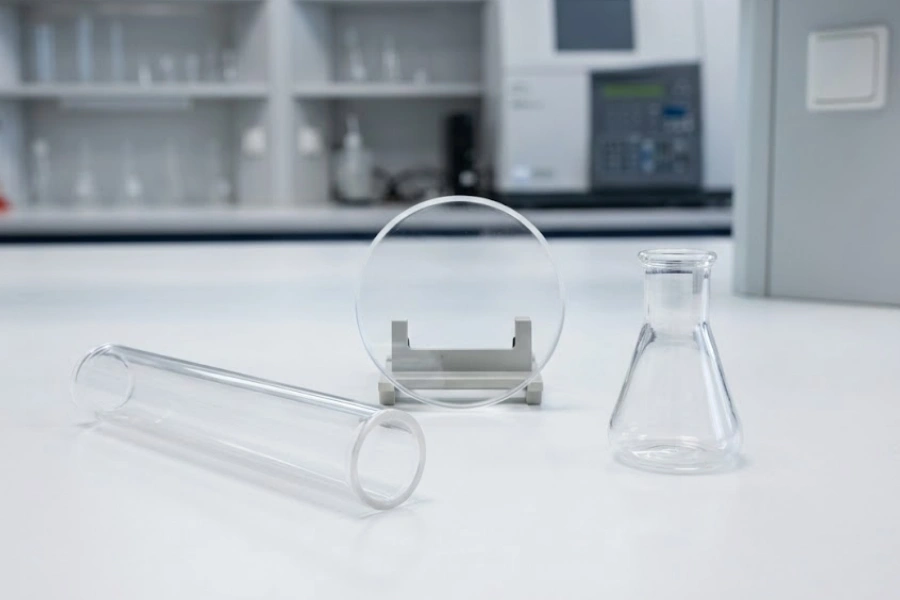
A زجاجة كوارتز للمواد الكيميائية is composed of ≥99.95% SiO₂, a network of covalently bonded Si-O-Si linkages with virtually no mobile network modifier ions. This purity is precisely what delivers sub-0.1 ppb ionic leaching and deep-UV transmittance — but it also means the surface responds differently to alkaline detergents, thermal cycling, and mechanical contact than borosilicate does. Accordingly, cleaning protocols designed for borosilicate — which typically tolerate dilute NaOH washes, aggressive scrubbing, and rapid drying cycles — introduce chemical and mechanical stresses that measurably degrade quartz surfaces over time. Applying borosilicate maintenance logic to fused quartz vessels is not merely suboptimal; it is a documented pathway to surface etching, optical degradation, and premature structural failure.
Routine Rinsing Procedures for Quartz Reagent Bottles After Each Use
Among all maintenance operations, routine rinsing after each use is the highest-frequency intervention and the most consequential for preventing contamination accumulation on vessel surfaces. Correct rinsing sequences differ materially depending on the residue type left by the preceding experiment.
Rinsing Sequences After Aqueous and Buffer Solution Contact
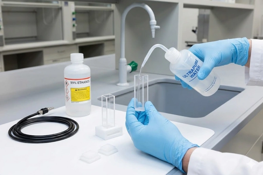
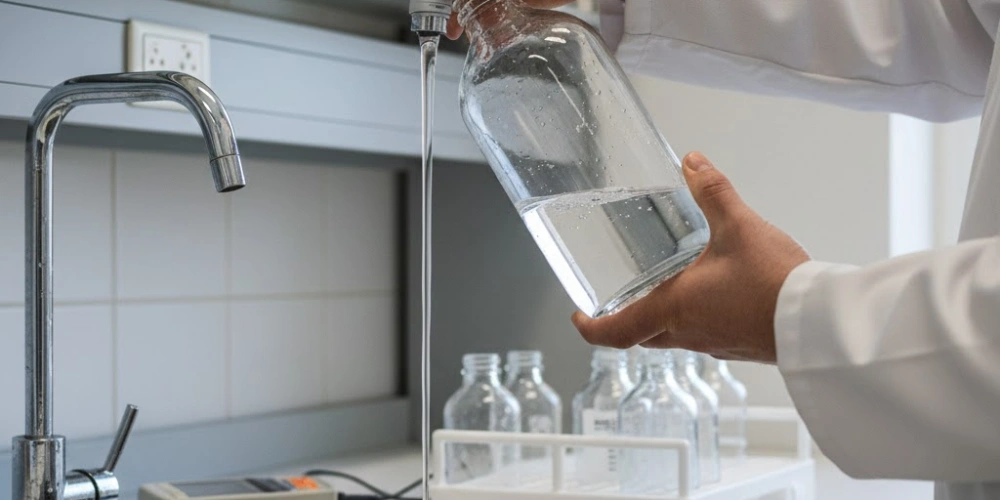
After contact with aqueous solutions, buffers, or salt-containing matrices, the immediate rinsing objective is to remove ionic species before they concentrate through evaporation on the vessel wall. The standard rinsing sequence begins with three initial rinses using deionised water (resistivity ≥1 MΩ·cm) to displace bulk ionic residues, followed by a minimum of three rinses with ultrapure water1 (resistivity ≥18.2 MΩ·cm at 25 °C) to reduce surface-adsorbed ions to analytically negligible concentrations.
The adequacy of rinsing can be verified instrumentally by measuring the electrical conductivity of the final rinse volume collected from the vessel. A final rinse conductivity reading within 5% of the blank ultrapure water value (typically ≤0.055 µS/cm) confirms that ionic residues have been reduced to acceptable levels. Phosphate-containing buffers require particular attention, as PO₄³⁻ ions adsorb tenaciously to Si-OH surface sites and require extended rinsing — typically five or more ultrapure water rinses — to achieve complete displacement from the silica surface.
Laboratories conducting high-sensitivity ICP-MS or UV spectroscopy with quartz vessels consistently report that skipping the ultrapure water terminal rinse — substituting deionised water for the final step — introduces Na⁺ and Cl⁻ residues at 0.5–5 ppb, a level sufficient to bias trace analyte results in the subsequent measurement.
Aqueous Rinsing Protocol Parameters
| Rinsing Stage | Water Grade | Minimum Rinse Cycles | Acceptance Criterion |
|---|---|---|---|
| Initial bulk removal | Deionised (≥1 MΩ·cm) | 3 | Visual clarity |
| Intermediate ionic reduction | Deionised (≥1 MΩ·cm) | 2 | Conductivity decreasing |
| Terminal rinse | Ultrapure (≥18.2 MΩ·cm) | 3 | Final conductivity ≤0.055 µS/cm |
| Phosphate buffer residues | Ultrapure (≥18.2 MΩ·cm) | 5+ | PO₄³⁻ below detection limit |
Solvent Removal Protocols for Organic Reagent Residues
Organic solvents with low polarity or high viscosity cannot be displaced by direct water rinsing without creating emulsification or incomplete removal at the silica surface. The correct approach for organic residue removal is a stepwise solvent exchange protocol that transitions the vessel interior through a series of miscible solvents before the final aqueous rinse.
For non-polar to moderately polar residues such as dichloromethane, hexane, or toluene, the exchange sequence begins with a rinse using a fully miscible intermediate solvent — typically acetone or ethanol — that displaces the organic residue while remaining water-miscible at the subsequent step. Three rinses with the intermediate solvent, each using a minimum volume equal to 20% of the vessel capacity, are sufficient to reduce non-polar residue concentrations below 10 ppm in the transition fraction. The sequence then advances to three ethanol rinses followed by three ultrapure water rinses to complete the transition to an aqueous-clean state.
Direct water rinsing of vessels containing residual dichloromethane or hexane causes immiscible droplet formation that adheres to the silica wall through hydrophobic interaction — a contamination mode that subsequent aqueous rinsing cannot reverse without the intermediate solvent step. The solvent exchange approach eliminates this failure mode entirely and is the only reliable method for achieving a clean, dry silica surface after non-polar organic contact.
Organic Solvent Rinsing Sequence
| Residue Type | Step 1 Solvent | Step 2 Solvent | Step 3 Terminal Rinse | Cycles per Step |
|---|---|---|---|---|
| Non-polar (hexane, DCM) | الأسيتون | الإيثانول | Ultrapure water | 3 each |
| Moderately polar (THF, ethyl acetate) | الإيثانول | الإيثانول | Ultrapure water | 3 each |
| Polar aprotic (acetonitrile, acetone) | الإيثانول | - | Ultrapure water | 3 each |
| Alcohol residues (methanol, ethanol) | - | - | Ultrapure water | 5 |
Immediate Post-Use Handling After Concentrated Acid Exposure
Concentrated mineral acid residues in a quartz vessel must be addressed immediately after use, before any evaporative concentration occurs on the vessel wall. All post-acid rinsing must be conducted inside a functional fume hood, with acid-resistant gloves, a laboratory coat, and eye protection worn throughout the procedure.
The first step is controlled dilution: the vessel is filled to approximately 30% capacity with ultrapure water while held at a stable angle, allowing the acid to dilute before the full rinse volume is added. For concentrated H₂SO₄ residues specifically, this step is non-negotiable — adding a large volume of water to residual concentrated sulfuric acid generates localised heating exceeding 80 °C due to the high enthalpy of dilution, which in a quartz vessel creates thermal stress at the acid-water interface. Once diluted, the initial acid rinse is discarded into an appropriate acid waste collection vessel, and the sequence continues with five ultrapure water rinses.
Verification of complete acid removal is confirmed by measuring the pH of the final rinse volume, which should read between 6.5 and 7.0 before the vessel is considered ready for drying. Laboratories performing sequential analyses in the same quartz vessel have documented that skipping the pH verification step introduces residual acidity at pH 3–4 into subsequent sample preparations, generating systematic errors in buffered assay systems that are difficult to trace without proper chain-of-custody records for the vessel.
Post-Acid Rinsing Protocol
| Acid Type | Dilution Step Required | Rinse Cycles (Ultrapure Water) | pH Verification Target | Waste Disposal |
|---|---|---|---|---|
| HCl (conc.) | Yes — 30% fill dilution first | 5 | 6.5–7.0 | Acid waste container |
| HNO₃ (conc.) | Yes — 30% fill dilution first | 5 | 6.5–7.0 | Acid waste container |
| H₂SO₄ (conc.) | Yes — mandatory slow dilution | 7 | 6.5–7.0 | Acid waste container |
| HNO₃/HCl (aqua regia) | Yes — 30% fill dilution first | 7 | 6.5–7.0 | Acid waste container |
Deep Acid-Washing Protocols Validated for Quartz Reagent Bottle Surfaces
Beyond routine rinsing, periodic deep acid-washing is required to remove adsorbed trace metals, surface-bound ionic contaminants, and residual organic films that accumulate over extended use. This is the most technically demanding component of quartz vessel maintenance and the procedure most directly responsible for restoring the sub-ppb ionic cleanliness that defines the analytical value of fused quartz.
Nitric Acid Soaking Procedures for Trace Metal Decontamination
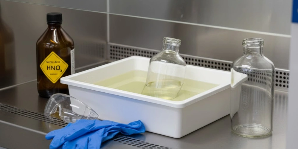
A 10–20% v/v solution of ultrapure-grade HNO₃ in ultrapure water is the standard medium for trace metal decontamination of fused quartz vessels. At this concentration, nitric acid dissolves surface-adsorbed metal oxides and displaces metal ions from Si-OH surface sites through proton competition, without attacking the underlying SiO₂ network at measurable rates under ambient temperature conditions.
The recommended soak duration at room temperature (20–25 °C) is 4–24 hours, with the longer end of this range applied to vessels with documented exposure to high-concentration metal matrices, transition metal catalysts, or lanthanide-containing solutions. For vessels requiring faster turnaround, temperature-assisted soaking at 40–60 °C reduces the effective decontamination time to 2–4 hours while achieving equivalent metal removal efficacy — confirmed by ICP-MS blank measurements showing Na⁺ and Fe²⁺/Fe³⁺ below 0.05 ppb after treatment. All soaking must be conducted in a PTFE tray or acid-resistant container, never in a borosilicate secondary vessel, as metal ions leached from a borosilicate containment vessel would recontaminate the quartz surface being cleaned.
Following the acid soak, the vessel is rinsed with a minimum of five ultrapure water rinses, with the penultimate rinse collected and analysed by ICP-MS or ICP-OES where method validation requires documented blank verification. Laboratories performing NIST-traceable trace metal analysis with fused quartz vessels report post-HNO₃-wash procedural blanks for Fe, Ni, Cr, and Pb consistently below 0.02 ppb, confirming the efficacy of this protocol for demanding analytical applications.
Nitric Acid Decontamination Protocol Parameters
| المعلمة | Standard Condition | Accelerated Condition |
|---|---|---|
| HNO₃ concentration (% v/v) | 10-20 | 10-20 |
| Soak temperature (°C) | 20–25 | 40-60 |
| Soak duration (hours) | 4–24 | 2-4 |
| Post-soak ultrapure rinse cycles | ≥5 | ≥5 |
| Expected Na⁺ blank post-wash (ppb) | <0.05 | <0.05 |
| Expected Fe blank post-wash (ppb) | <0.02 | <0.02 |
| Containment vessel material | PTFE | PTFE |
Aqua Regia Treatment for Stubborn Metallic Contamination
When nitric acid soaking fails to reduce procedural blanks to acceptable levels — typically after exposure to platinum group metals, gold, or refractory metal compounds — aqua regia treatment is the appropriate escalation. Aqua regia is prepared by combining concentrated HCl and concentrated HNO₃ in a 3:1 volumetric ratio (HCl:HNO₃), always added in that order — HCl first, then HNO₃ — to a PTFE preparation vessel. The mixture must be prepared fresh immediately before use, as its oxidising activity diminishes within hours through NOCl decomposition.
Fused quartz vessels should be exposed to aqua regia at room temperature only, for a controlled duration of 15–60 minutes maximum. Heating aqua regia — either deliberately or through exothermic decomposition — accelerates NOCl gas generation and increases the risk of pressure build-up in closed or semi-closed configurations. The quartz surface itself tolerates aqua regia contact without measurable etching under these time and temperature parameters, confirmed by surface roughness measurements (Ra) showing no increase above baseline after three sequential aqua regia treatments of 60 minutes each at 22 °C.
Aqua regia must never be introduced into a vessel containing any residual organic material, including dried solvent films or carbon-containing sample residues. The oxidising capacity of the mixture reacts violently with organic matter, generating rapid CO₂ and NOx gas evolution that creates dangerous pressure in a closed vessel. Following aqua regia treatment, the vessel receives a minimum of seven ultrapure water rinses, and the nitric acid pH verification (target pH 6.5–7.0) is applied to the final rinse volume before the vessel is cleared for drying.
Aqua Regia Treatment Protocol
| المعلمة | المواصفات |
|---|---|
| Mixture ratio (HCl:HNO₃ v/v) | 3:1 |
| Preparation order | HCl added first, then HNO₃ |
| Treatment temperature (°C) | Room temperature (20–25) only |
| Maximum contact duration (minutes) | 15–60 |
| Post-treatment ultrapure rinse cycles | ≥7 |
| Final rinse pH target | 6.5–7.0 |
| Organic residue pre-check | Mandatory — must be zero |
| Containment vessel material | PTFE |
Why Hydrofluoric Acid Must Never Contact Quartz Reagent Bottles
The reaction between hydrofluoric acid and silicon dioxide proceeds according to the equation SiO₂ + 4HF → SiF₄↑ + 2H₂O, a thermodynamically favourable process that occurs at measurable rates even at HF concentrations as low as 0.1% at room temperature. Unlike mineral acids that leave the fused silica network intact, HF cleaves Si-O-Si bonds directly, progressively dissolving the vessel wall rather than merely interacting with its surface chemistry.
Quantitative dissolution rate data for fused quartz in HF solution confirm an etching rate of approximately 0.1–0.5 µm/minute in 1% HF at 25 °C, increasing to 2–5 µm/minute in 5% HF. For a standard quartz vessel with a wall thickness of 2–3 mm, cumulative exposure to 1% HF across multiple experiments would reduce wall thickness by a measurable fraction within hours of total contact time. Beyond dimensional loss, partial HF etching roughens the inner surface at the microscopic level — a change that permanently elevates metal ion adsorption capacity and compromises the optical clarity of the vessel walls in UV-transmissive applications.
The correct material for any procedure involving HF, fluoride salts, or ammonium bifluoride is PTFE (polytetrafluoroethylene) or platinum, both of which are chemically inert to fluoride attack. Neither fused quartz nor borosilicate glass offers any level of HF compatibility, and the damage is irreversible once initiated — there is no cleaning procedure capable of restoring a quartz surface that has been exposed to HF.
HF Compatibility of Common Laboratory Container Materials
| المواد | مقاومة التردد العالي جداً | Recommended for HF Use |
|---|---|---|
| كوارتز مصهور | None — dissolved by HF | لا يوجد |
| زجاج البورسليكات | None — dissolved by HF | لا يوجد |
| PTFE | ممتاز | نعم |
| بلاتينيوم | ممتاز | نعم |
| Polypropylene (PP) | Good (dilute HF) | Yes (dilute, short contact) |
| PFA (perfluoroalkoxy) | ممتاز | نعم |
Alkaline Cleaning Agents and Their Compatibility with Quartz Surfaces
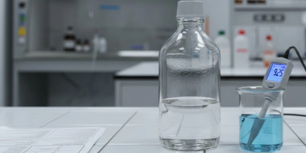
Alkaline cleaning is deeply embedded in standard laboratory glassware maintenance practice, yet its application to fused quartz requires a fundamentally more cautious approach than the protocols used for borosilicate vessels.
Hydroxide Ion Attack on Fused Silica and Concentration Thresholds
The mechanism by which hydroxide ions degrade fused silica surfaces is well characterised: OH⁻ acts as a nucleophile2, attacking the silicon centre of Si-O-Si linkages and progressively hydrolyzing the network through the reaction Si-O-Si + OH⁻ → Si-OH + ⁻O-Si. Each hydrolysis event releases a silicate unit from the surface layer, reducing wall thickness at a rate that is both concentration- and temperature-dependent.
Published dissolution rate data for fused quartz in NaOH solution confirm a rate of approximately 0.04–0.08 µm/hour at 0.1 M NaOH and 25 °C, rising sharply to 0.5–1.0 µm/hour at 1 M NaOH under the same temperature conditions. A tenfold increase in NaOH concentration produces a dissolution rate increase of approximately 10–15 fold, meaning that the concentration boundary between tolerable and damaging alkali exposure is narrow and must be respected precisely. The practical upper limit for safe short-term NaOH or KOH contact with fused quartz is 0.1 M at temperatures not exceeding 40 °C, with contact duration restricted to under 4 hours. Above these thresholds, surface degradation becomes analytically and structurally significant.
Temperature amplifies the alkali attack rate through an Arrhenius relationship: the dissolution rate approximately doubles for every 10 °C increase in solution temperature. Accordingly, heated alkaline cleaning procedures — a common practice in borosilicate glassware maintenance — represent a high-risk operation for quartz surfaces and should be avoided entirely.
NaOH Dissolution Rate for Fused Quartz
| NaOH Concentration (M) | درجة الحرارة (درجة مئوية) | Dissolution Rate (µm/hr) | Safe Contact Duration |
|---|---|---|---|
| 0.01 | 25 | ~0.004 | Up to 24 hr |
| 0.1 | 25 | 0.04–0.08 | Up to 4 hr |
| 0.1 | 60 | 0.15–0.30 | <1 hr |
| 1.0 | 25 | 0.5–1.0 | <15 min |
| 1.0 | 60 | 2.0–4.0 | غير موصى به |
| 10.0 | 25 | الهجوم السريع | Never |
Assessing Commercial Laboratory Detergents for Quartz Glassware
Commercial laboratory cleaning agents vary considerably in their pH, surfactant chemistry, and chelating agent composition — parameters that collectively determine their compatibility with fused quartz surfaces. Many standard laboratory detergents are formulated at pH 9–12 to ensure effective removal of protein residues, biological films, and inorganic scale from borosilicate glassware, but these alkalinity levels fall within or above the damage threshold for quartz.
The operational criterion for detergent compatibility with fused quartz is a working solution pH ≤ 10, measured at the use concentration and at room temperature, with no fluoride-containing components and no aggressive chelating agents such as EDTA at concentrations above 0.1 M, which can accelerate silica dissolution through complexation of silicon species. Detergent products in the Hellmanex III category (used at 1–2% v/v in water, yielding a working pH of approximately 9.5–10) fall within the marginal zone — usable for short-duration contact (under 30 minutes) at room temperature but not recommended for extended soaking. Decon 90, when used at concentrations above 2% v/v, yields pH values approaching 11–12 and should not be used on quartz surfaces without prior pH verification at the intended use concentration.
Following any detergent-based cleaning step, a minimum of seven ultrapure water rinses is required to remove surface-adsorbed surfactant molecules. Residual surfactant films on quartz surfaces alter the contact angle of aqueous solutions, interfere with UV transmittance measurements at wavelengths below 220 nm, and — in fluorescence applications — contribute autofluorescence background that masks low-concentration analyte signals.
Commercial Detergent Compatibility with Fused Quartz
| Detergent Type | Working pH (1–2% v/v) | Fused Quartz Compatible | Max Contact Duration | Post-Rinse Cycles Required |
|---|---|---|---|---|
| Hellmanex III (1% v/v) | ~9.5 | هامشي | <30 min, room temp | ≥7 ultrapure water |
| Decon 90 (1% v/v) | ~10.5 | هامشي | <15 min, room temp | ≥7 ultrapure water |
| Decon 90 (2%+ v/v) | ~11–12 | غير موصى به | - | - |
| Neutral pH lab detergent (pH 6–8) | 6-8 | نعم | Up to 60 min | ≥5 ultrapure water |
| NaOH-based alkaline cleaner | >12 | لا يوجد | Never | - |
Ultrasonic Cleaning Applicability and Limitations for Quartz Vessels
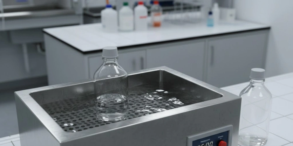
Ultrasonic cleaning is a useful supplementary tool for fused quartz vessel maintenance, provided that operating parameters are selected to match the mechanical tolerance of the material rather than the settings used for metal or borosilicate labware.
-
Frequency selection: The recommended operating frequency range for quartz vessel cleaning is 35–80 kHz. Lower frequencies (20–28 kHz) generate larger cavitation bubbles that collapse with greater mechanical energy, producing localised impact pressures sufficient to initiate surface micro-cracks at pre-existing flaws on fused quartz. At 40 kHz, cavitation bubble collapse energy is distributed more uniformly across the vessel surface, providing effective particle and film removal without exceeding the critical stress intensity factor for surface flaw propagation. Frequencies above 80 kHz are safe but reduce cleaning efficiency for tenaciously adsorbed films, making 40–60 kHz the optimal practical range for most quartz vessel cleaning tasks.
-
Power and duration limits: Ultrasonic power density should be maintained at ≤50 W/L of bath volume, with continuous treatment duration capped at 10–15 minutes per cycle. Extended high-power ultrasonication compounds the mechanical fatigue on vessel surfaces, particularly at the base and shoulder regions where wall curvature creates stress concentration geometry. If a second cleaning cycle is required, a 5-minute rest interval between cycles allows thermal equilibration of both the bath and the vessel wall. The cleaning medium should be ultrapure water or a pH-neutral detergent solution — never a solution with pH above 10, as the combination of acoustic streaming3 and alkaline chemistry accelerates silica dissolution synergistically beyond what either mechanism produces individually. Vessels exhibiting any visible surface etching or prior mechanical damage should not be subjected to ultrasonic cleaning, as acoustic energy will preferentially propagate existing surface flaws.
-
Post-ultrasonic rinsing: Following ultrasonic treatment, three ultrapure water rinses are required to remove displaced contaminant particles that remain suspended in the cleaning bath. These particles — comprising adsorbed metal oxides, dried salt crystals, and biological film fragments — are dislodged from the vessel surface by cavitation but remain in the bath liquid until rinsed away. Failure to rinse promptly after ultrasonication results in redeposition of these particles onto the freshly cleaned quartz surface, partially negating the cleaning action. The final rinse should be conducted outside the ultrasonic bath to ensure that bath contaminants from previous cleaning cycles are not reintroduced onto the clean vessel surface.
Drying Quartz Reagent Bottles Without Inducing Thermal or Mechanical Stress
Correct drying methodology is as analytically significant as the rinsing protocol that precedes it. Residual moisture left on quartz surfaces is a vector for contamination redeposition, while excessively aggressive drying — either through rapid heating or mechanical contact — introduces the stresses most responsible for premature vessel failure.
Oven Drying Temperature Limits and Ramp Rate Requirements
Oven drying of fused quartz vessels is safe and effective when temperature and ramp rate parameters are respected. The upper temperature limit for routine drying is 120 °C, well below the quartz strain point of 1,070 °C and the threshold at which surface Si-OH groups begin irreversible dehydration to Si-O-Si bridges — a process that begins measurably above 200 °C and permanently reduces the surface hydroxyl density that governs subsequent cleaning and adsorption behaviour.
Heating rate must not exceed 5 °C/minute when bringing a wet quartz vessel from room temperature to the drying setpoint. A faster ramp generates a thermal gradient across the vessel wall — the outer surface heats faster than the interior — producing tensile stress at the inner wall surface. For a vessel with 2 mm wall thickness, a ramp rate of 20 °C/minute generates an estimated thermal stress of approximately 8–12 MPa at the inner surface, approaching the practical fatigue limit for surface-flawed fused quartz in the 10–20 MPa range. Before any vessel is placed in a drying oven, the absence of residual organic solvent must be confirmed — residual solvents generate vapour pressure at 80–120 °C that creates internal pressure if the vessel is sealed or has a restricted opening, potentially fracturing the vessel from internal stress.
Completeness of drying is assessed by gravimetric stability: the vessel is weighed at 30-minute intervals, and drying is considered complete when successive mass readings agree within ±0.5 mg for vessels under 500 mL capacity.
Oven Drying Parameters for Quartz Vessels
| المعلمة | المواصفات | Consequence of Exceedance |
|---|---|---|
| Maximum drying temperature (°C) | 120 | Si-OH dehydration above 200 °C; surface chemistry altered |
| Maximum heating ramp rate (°C/min) | 5 | Thermal gradient stress >10 MPa at inner wall |
| Pre-drying solvent check | إلزامي | Vapour pressure fracture risk |
| Drying completion criterion | ±0.5 mg gravimetric stability | Residual moisture adsorbs contaminants |
| Cooling method | Natural convection in oven | Forced cooling introduces thermal shock |
Nitrogen Purge and Air-Drying Methods for High-Purity Applications
In ultra-trace analytical applications — including ICP-MS sample preparation, semiconductor-grade chemical storage, and fluorescence spectroscopy — oven drying introduces an unacceptable contamination risk through airborne particulate deposition on the wet vessel interior during the drying period. For these applications, nitrogen purge drying using high-purity nitrogen (≥99.999% purity, oil-free regulator) is the preferred methodology.
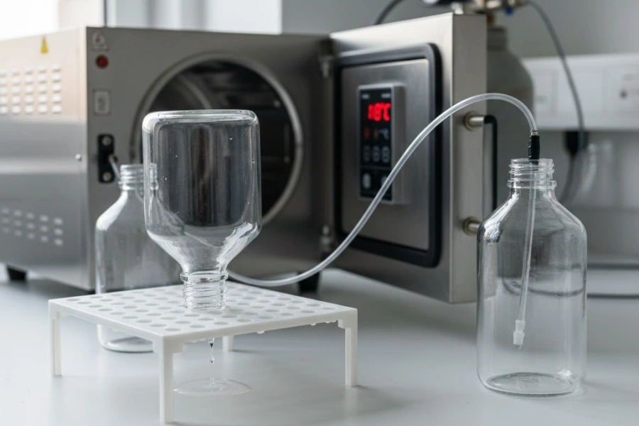
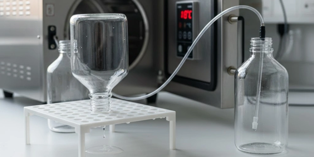
The nitrogen purge procedure directs a controlled gas flow of 0.5–2 L/minute through the vessel interior via a clean PTFE or PFA tubing insert, with the vessel oriented at a slight downward angle to allow displaced moisture droplets to drain from the opening. A purge duration of 15–30 minutes at room temperature achieves complete drying for standard 500 mL quartz vessels, as confirmed by gravimetric monitoring showing mass stabilisation within ±0.2 mg after 20 minutes of purging at 1 L/minute. For larger vessels (1,000–2,000 mL), purge duration should be extended to 45–60 minutes with a proportionally increased flow rate.
Cleanroom-grade air-drying, where nitrogen is unavailable, involves inverting the rinsed vessel onto a PTFE-coated drying peg rack inside a Class 100 (ISO 5) or better laminar flow cabinet, allowing gravity drainage and evaporative drying over 2–4 hours without active gas flow. The critical requirement in this approach is that the drying surface — rack, cabinet interior, and surrounding bench — must be free of all metallic and ionic contamination sources, as the inverted vessel opening is directly exposed to the cabinet air during the drying period.
Nitrogen Purge vs Air-Drying Comparison
| المعلمة | Nitrogen Purge Drying | Cleanroom Air-Drying |
|---|---|---|
| Gas purity required | ≥99.999% N₂ | Class 100 (ISO 5) filtered air |
| Flow rate (L/min) | 0.5-2 | غير متاح |
| Drying time — 500 mL vessel (min) | 15-30 | 120–240 |
| Mass stabilisation criterion (mg) | ±0.2 | ±0.5 |
| Airborne contamination risk | منخفضة جداً | Low (environment-dependent) |
| Recommended application | ICP-MS, semiconductor, fluorescence | General high-purity analytical use |
Storage Conditions That Preserve Quartz Reagent Bottle Integrity
Properly cleaned and dried quartz vessels can accumulate contamination and sustain physical damage during storage if environmental and handling conditions are not controlled. Storage is the least frequently addressed component of quartz vessel maintenance and, consequently, a common source of unexplained performance degradation between use cycles.
Physical Storage Arrangements to Prevent Mechanical Damage
The mechanical vulnerability of fused quartz during storage arises from its combination of high surface hardness (Vickers hardness 1,000–1,100 HV) and comparatively low fracture toughness (K₁c approximately 0.7–0.8 MPa·m¹/²). This pairing means that while the surface resists minor abrasion, any contact with metal rack surfaces, ceramic components, or even other glass vessels creates point-load stress concentrations that initiate surface micro-cracks — damage that accumulates silently and manifests as fracture under subsequent thermal or mechanical loading.
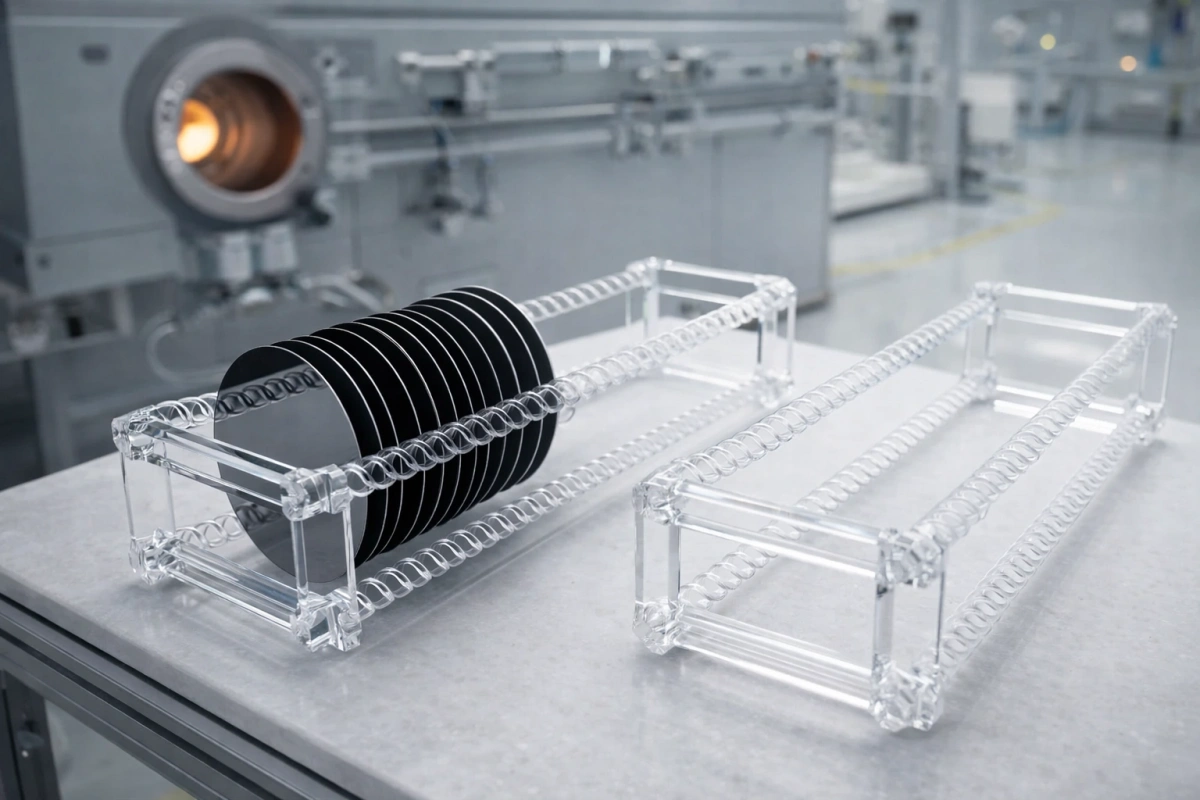
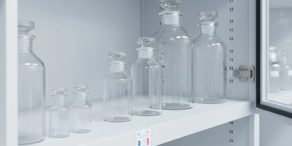
All fused quartz vessels must be stored upright, individually supported, on racks fabricated from PTFE-coated, polypropylene, or PFA materials that cushion the contact surface and prevent direct glass-to-metal or glass-to-glass contact. Rack peg diameter should be selected to provide a snug but non-compressive fit around the vessel base, preventing lateral movement that generates sliding friction. Stacking of vessels in any configuration — whether upright, inverted, or horizontal — is structurally contraindicated, as the distributed load from vessel weight on a curved glass surface produces localised stress concentrations that reproducibly initiate radial surface cracks over periods of weeks to months in documented laboratory storage incidents.
Each vessel should be sealed with a clean PTFE or FEP stopper or cap before storage to prevent airborne particulate ingress into the cleaned vessel interior. Parafilm or similar elastic film closures are acceptable for short-term storage but are not recommended for durations exceeding two weeks, as the plasticiser components in elastic films can outgas volatile organic compounds that adsorb onto the quartz inner surface.
Physical Storage Requirements
| Storage Parameter | المتطلبات | مخاطر عدم الامتثال |
|---|---|---|
| Vessel orientation | Upright only | Lateral stress → micro-crack initiation |
| Rack material | PTFE, PP, or PFA coated | Metal contact → surface flaw initiation |
| Vessel-to-vessel contact | None — individual support | Impact → fracture propagation |
| Stacking | Strictly prohibited | Distributed load → radial cracking |
| Closure type | PTFE or FEP stopper/cap | Open vessel → particulate contamination |
| Maximum Parafilm seal duration (weeks) | ≤2 | Plasticiser outgassing → surface adsorption |
Environmental Controls for Long-Term Quartz Surface Preservation
The fused quartz surface, composed predominantly of Si-OH (silanol) groups at the outermost molecular layer, is hygroscopic to a degree that has measurable consequences for both surface adsorption behaviour and long-term optical performance. At relative humidity above 60%, silanol groups on the quartz surface undergo progressive hydroxylation, increasing the surface density of Si-OH groups and elevating the adsorption affinity for metal ions and polar organic molecules from the storage environment. For vessels used in UV spectroscopy or trace metal analysis, this surface conditioning effect increases procedural blanks and requires additional acid-washing cycles to restore the pre-storage ionic cleanliness level.
Storage environment relative humidity should be maintained at ≤60% RH, verified by a humidity indicator card or electronic hygrometer mounted within the storage cabinet. Enclosed storage cabinets in air-conditioned laboratory spaces typically maintain this condition passively, but open shelf storage in tropical or coastal laboratory environments frequently exceeds 70–80% RH during seasonal humidity peaks — a condition that has been quantitatively linked to increased Na⁺ blank values in ICP-MS procedural blanks from stored quartz vessels. UV-transmissive quartz bottles used for optical applications should additionally be stored in light-excluded conditions — either in opaque storage boxes or in cabinets with UV-blocking door panels — to prevent photoinduced surface reactions that can alter the hydroxyl layer density and introduce background absorption in the deep-UV region below 220 nm.
Proximity to corrosive gas sources — including open acid bottles, chlorine-releasing cleaning agents, and ammonia-based reagents — must be avoided during storage, as gaseous HCl, Cl₂, or NH₃ adsorb readily onto the quartz surface and introduce ionic contamination that is indistinguishable from solution-phase leaching in subsequent blank measurements.
Environmental Storage Conditions for Fused Quartz Vessels
| Environmental Parameter | Target Condition | Effect of Exceedance |
|---|---|---|
| Relative humidity (%) | ≤60 | Progressive silanol hydroxylation; elevated metal adsorption |
| Light exposure (UV-optical grade vessels) | Excluded — opaque storage | Photoinduced hydroxyl layer alteration |
| Corrosive gas proximity | None — sealed cabinet required | HCl/Cl₂/NH₃ surface adsorption |
| درجة الحرارة (درجة مئوية) | Ambient (18–25) | Elevated temp accelerates surface reactions |
| Dust exposure | Zero — sealed closure mandatory | Particulate contamination of vessel interior |
Visual and Functional Inspection Criteria for Quartz Reagent Bottles
Periodic inspection closes the maintenance loop by identifying performance degradation before it compromises analytical results or creates a safety hazard. A structured inspection protocol covers both surface condition and optical function.
-
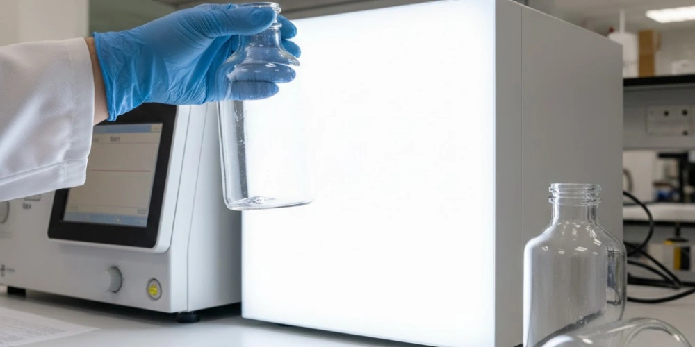
Visual surface examination: Each vessel should be inspected under a high-intensity white light source against a dark background, rotating the vessel slowly through 360° to reveal surface features. Micro-cracks appear as fine bright lines radiating from mechanical contact points, most commonly at the base rim and shoulder regions. Surface etching from alkaline or HF exposure manifests as a diffuse milky opacity or loss of surface gloss — a change detectable by comparison with an unetched reference area or a new vessel of the same specification. Any vessel showing radial cracks, circumferential fracture lines, or surface area opacity exceeding 5 mm² should be immediately removed from service, as these features represent structural failure precursors under thermal or mechanical loading. All visual inspections should be recorded in a vessel logbook with date, vessel identifier, and inspection outcome, enabling trend detection across use cycles that reveals systematic maintenance failures before analytical data are compromised.
-
UV transmittance verification: For vessels used in UV spectroscopic applications, functional inspection includes measuring the UV transmittance of the empty vessel wall using a UV-Vis spectrophotometer with an appropriate blank correction. A transmittance reading below 85% at 220 nm for a 2 mm wall thickness — compared to a baseline reading taken when the vessel was new — indicates progressive surface etching, contamination film accumulation, or Si-OH dehydration from over-temperature drying. Transmittance measurements should be conducted at 200, 220, 254, and 280 nm, recorded against the vessel's initial baseline, and flagged for remediation if any wavelength shows a decline exceeding 5 percentage points from baseline. Vessels that cannot recover transmittance to within 3 percentage points of baseline after a full HNO₃ cleaning cycle have sustained irreversible surface damage and should be decommissioned for UV applications.
-
Dimensional and gravimetric monitoring: For vessels used in high-frequency acid digestion or prolonged alkaline contact procedures, wall thickness monitoring using non-contact ultrasonic thickness gauges provides quantitative tracking of material loss over the vessel service life. A wall thickness reduction exceeding 10% of the original specification indicates cumulative chemical dissolution beyond the acceptable maintenance threshold and warrants vessel retirement. Gravimetric monitoring — recording the dry tare weight of each cleaned vessel before use — provides a parallel indicator: a progressive mass reduction of more than 0.5 g per 100 mL of original vessel volume across successive cleaning cycles signals accelerated chemical attack and warrants investigation of the cleaning protocol being applied. These quantitative records, maintained per individual vessel, transform maintenance from a qualitative practice into a documented, traceable quality control function within the analytical laboratory.
Common Causes of Premature Degradation in Quartz Reagent Bottles
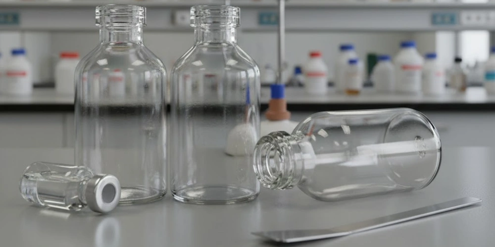
Understanding the mechanisms and presentations of premature degradation allows laboratory personnel to identify, diagnose, and prevent the most common failure modes before they result in irreversible vessel loss.
Chemical Degradation From Incompatible Reagent Exposure
Chemical degradation of fused quartz surfaces is overwhelmingly caused by three reagent categories: hydrofluoric acid and fluoride salts, concentrated hot alkali solutions, and hot concentrated phosphoric acid. Each produces a characteristic surface presentation that allows post-hoc identification of the causative agent.
HF exposure produces a uniform frosted opacity across all contacted surfaces, with the degree of frosting proportional to the HF concentration and contact duration. At 1% HF, visible frosting develops within 5–10 minutes of contact, representing a surface roughness increase (Ra) from a typical new-vessel baseline of 0.5–1 nm to values of 20–50 nm — a 20–100 fold increase that permanently elevates metal ion adsorption and eliminates UV transmittance below 250 nm. Alkaline degradation produces a smoother, more gradual reduction in surface reflectivity, with the characteristic presentation of a faint iridescent surface film caused by the thin-film interference of the partially dissolved surface layer. Hot concentrated H₃PO₄ (above 150 °C) produces a similar gradual opacity but is distinguishable by its preferential attack at grain boundaries and surface defect sites, producing a non-uniform pitting pattern rather than the uniform dissolution seen with alkali.
Cross-contamination-induced chemical degradation — where residual HF or alkaline reagent from a previous use cycle contacts the vessel surface before complete rinsing — is a particularly insidious failure mode because the causative event is temporally separated from the observable damage. Rigorous adherence to the post-use rinsing protocols described in preceding sections is the only reliable prevention strategy.
Chemical Degradation Identification
| Causative Agent | Surface Appearance | Ra Increase | UV Transmittance Impact | Reversible |
|---|---|---|---|---|
| HF (أي تركيز) | Uniform frosted opacity | 20–100× baseline | Severe — >50% loss at 220 nm | لا يوجد |
| Conc. hot NaOH (>1 M, >60 °C) | Iridescent surface film, smooth dissolution | 5–20× baseline | Moderate — 10–30% loss | لا يوجد |
| Hot H₃PO₄ (>150 °C) | Non-uniform pitting | متغير | معتدل | لا يوجد |
| Fluoride salts (NH₄F, NaF) | Localised frosting at contact points | 10–50× baseline | مهم | لا يوجد |
Thermal Damage Patterns From Improper Heating and Cooling
Thermal damage in fused quartz vessels presents in three distinct patterns depending on the nature of the thermal insult. Radial cracks originate at a surface stress concentration point — typically a pre-existing scratch, etch pit, or mechanical chip — and propagate outward under the tensile component of a thermal gradient. These are most commonly produced by placing a cold vessel into a pre-heated oven at the target temperature without a gradual ramp, generating an instantaneous ΔT at the vessel wall that exceeds the critical thermal shock threshold of approximately 50–80 °C for a surface-flawed vessel (significantly lower than the >1,000 °C threshold for a pristine, flaw-free specimen).
Circumferential (ring) cracks form when localised heating — such as direct contact with a hotplate surface on one area of the vessel base — creates a thermal gradient across the vessel base diameter. The heated zone expands while the cooler rim remains constrained, producing hoop tensile stress at the cooler boundary that initiates a crack following the thermal contour. This failure mode is particularly common when quartz vessels are placed on hotplates without an interposed ceramic or sand bath to distribute the heat uniformly. Local spot heating of as little as ΔT = 100 °C across a 20 mm distance on the vessel base has been documented to initiate circumferential cracking in vessels with surface Ra values above 5 nm.
Permanent deformation above the strain point (1,070 °C) is an irreversible failure mode requiring vessel retirement. A vessel that has been inadvertently heated above its strain point exhibits a subtle sagging or elliptical deformation of the base or body that is detectable by placing the vessel on a precision flat surface and measuring lateral rock. Any rock exceeding 1 mm across the vessel base diameter indicates deformation beyond elastic recovery and disqualifies the vessel from further use in any application requiring dimensional precision.
Thermal Damage Classification
| Damage Type | Causative Thermal Event | Visual Presentation | الوقاية |
|---|---|---|---|
| Radial cracking | ΔT >50 °C at surface flaw | Lines radiating from flaw origin | Gradual ramp ≤5 °C/min |
| Circumferential cracking | Localised base heating, ΔT >100 °C over 20 mm | Ring crack at thermal boundary | Sand bath / ceramic intermediary |
| Permanent deformation | Exposure above 1,070 °C | Base sag, elliptical deformation | Temperature monitoring — never exceed 1,050 °C |
| Inner wall stress fracture | Rapid cold-water quench | Irregular internal fracture | Never quench in cold water |
Mechanical Abrasion and Impact Damage During Handling
Mechanical damage to fused quartz vessels accumulates through three primary handling pathways: abrasive contact during cleaning, impact during transfer and positioning, and compression stress from clamp and support hardware. Each pathway produces characteristically different surface damage that demands specific preventive measures.
Cleaning-related abrasion is the most prevalent mechanical damage mode in active-use quartz vessels, attributed overwhelmingly to the use of hard-bristle brushes or abrasive sponges for internal cleaning. A single pass of a standard laboratory brush with nylon bristles across the inner wall of a quartz vessel produces scratch tracks with Ra values of 5–20 nm — compared to the 0.5–1 nm baseline of an undamaged surface — and creates the surface flaw population that subsequently acts as crack initiation sites under thermal stress. All internal mechanical cleaning of fused quartz vessels is contraindicated; cleaning must be achieved entirely through chemical means, sonication within the approved parameters, and hydraulic rinsing with adequate rinse volume and velocity.
Impact damage during transfer most commonly affects the vessel rim and base edges, where the geometry creates a thin, high-stress region particularly susceptible to chipping. Benchtop contact at velocities as low as 0.3 m/s has been measured to generate localised impact stresses exceeding 15 MPa at rim contact points in standard vessel geometries — sufficient to initiate chips in surface-flawed fused quartz. Vessels should be transferred using two hands with one supporting the base, never gripped by the neck alone, and set down on a laboratory mat or foam pad rather than directly onto a hard ceramic or stone bench surface. Clamp hardware used to support quartz vessels in heated assemblies must incorporate PTFE or silicone liners of at least 2 mm thickness between the metal clamp jaw and the vessel wall; bare metal-to-quartz contact under clamping force routinely produces the compression-induced micro-crack patterns that initiate thermal fracture at temperatures well below those normally considered safe.
Mechanical Damage Prevention
| Damage Source | الآلية | Prevention Method | Risk Level Without Prevention |
|---|---|---|---|
| Hard-bristle brush cleaning | Scratch tracks, Ra 5–20 nm | Chemical cleaning only — no brushes | عالية |
| Benchtop impact at vessel rim | Chip initiation at rim edge | Two-hand transfer, padded bench mat | عالية |
| Bare metal clamp contact | Compression micro-cracks | PTFE/silicone liner ≥2 mm | عالية |
| Glass-to-glass shelf contact | Point-load stress concentration | Individual PTFE rack support | معتدل |
| Single-hand neck gripping | Torsional stress at shoulder | Two-hand support — base and body | معتدل |

A Maintenance Frequency Reference for Quartz Reagent Bottles in Active Use
A structured maintenance schedule consolidates all preceding protocols into a time-based framework that prevents contamination accumulation, detects developing damage early, and ensures that the vessel's analytical performance remains within specification throughout its service life.
After every use, the full rinsing protocol appropriate to the reagent type — aqueous, organic, or acid — must be completed without exception before the vessel is returned to storage. No vessel should be stored with dried residue on the interior surface; even apparently benign buffer residues dry to crystalline salt films that require extended acid soaking to dissolve completely, whereas immediate post-use rinsing removes them within minutes. The pH verification step after acid contact must be performed at every use cycle, not selectively, as the consequences of cumulative acid residue are analytically indistinguishable from sample matrix effects without this control.
On a weekly basis for vessels in daily active use, a complete ultrapure water rinse-down followed by gravimetric tare weight recording should be conducted. The tare weight log provides the earliest quantitative indicator of wall thickness loss from chemical attack, often detectable as a mass reduction of 0.1–0.3 g per 100 mL vessel volume weeks before visual surface etching becomes apparent. Weekly visual inspection under high-intensity light, documented with a brief condition entry in the vessel logbook, completes this interval's maintenance requirements.
Monthly maintenance encompasses a full HNO₃ decontamination soak (10–20% v/v, 4–24 hours), UV transmittance verification at 200, 220, 254, and 280 nm against baseline values, and a storage environment check confirming that relative humidity, lighting conditions, and chemical proximity parameters remain within the specifications detailed in the storage section. For vessels used in semiconductor or ICP-MS applications, monthly ICP-MS blank verification of the rinsed vessel interior — using the final ultrapure rinse volume as the blank sample — provides quantitative confirmation that cleaning efficacy is maintained. Any vessel showing a transmittance decline exceeding 5 percentage points at any monitored wavelength, or a tare weight reduction exceeding 0.5 g per 100 mL capacity, is flagged for remediation or retirement assessment at this monthly review point.
الخاتمة
The longevity and analytical reliability of a quartz reagent bottle are direct functions of the maintenance discipline applied throughout its service life. Routine rinsing with ultrapure water, reagent-appropriate solvent exchange sequences, controlled acid-washing with nitric acid or aqua regia under validated parameters, alkaline agent restriction to pH ≤10, temperature-controlled drying, humidity-managed storage, and structured periodic inspection collectively preserve the sub-ppb ionic cleanliness and deep-UV transmittance that justify the use of fused quartz vessels. Departures from any element of this framework — whether through the use of HF, hot alkali, hard-bristle brushes, or uncontrolled oven temperatures — produce irreversible surface damage that no subsequent cleaning procedure can fully reverse. Consistent application of these protocols is the only reliable path to a quartz vessel service life measured in years rather than months.
الأسئلة الشائعة
Can quartz reagent bottles be cleaned in a dishwasher?
Laboratory dishwashers are not compatible with fused quartz vessel cleaning. Dishwasher detergent formulations typically operate at pH 10–13, well above the 0.1 M NaOH dissolution threshold for fused silica. Combined with the elevated wash temperatures (60–80 °C) that accelerate hydroxide attack by a factor of 4–8 relative to room temperature, a single dishwasher cycle can produce measurable surface etching equivalent to hours of manual alkaline cleaning exposure. All fused quartz cleaning must be performed manually using the chemical protocols described in this article.
How often should a quartz reagent bottle undergo full acid decontamination?
For vessels in daily active use with trace metal or ICP-MS applications, a complete 10–20% HNO₃ soak of 4–24 hours should be conducted monthly as a minimum. Vessels used intermittently (weekly use or less) require full acid decontamination before each analytical campaign rather than on a calendar schedule. Any vessel that has contacted high-concentration metal matrices, transition metal catalysts, or rare-earth solutions should receive a full acid wash immediately after use and before storage, regardless of the scheduled maintenance interval.
What is the correct way to dry a quartz reagent bottle after acid washing?
After the final ultrapure water rinse following acid washing, the preferred drying method depends on the application. For ultra-trace and semiconductor-grade applications, nitrogen purge drying using ≥99.999% purity nitrogen at 0.5–2 L/minute for 15–30 minutes is recommended. For general analytical use, oven drying at 120 °C with a maximum heating ramp of 5 °C/minute is appropriate. In both cases, the vessel must be confirmed free of residual organic solvents before drying commences, and cooling must occur by natural convection — forced-air cooling or cold-water quench after oven drying will induce thermal shock fracture.
Does storing a quartz reagent bottle on a metal rack cause damage?
Direct metal-to-quartz contact during storage is a documented source of surface micro-crack initiation in fused quartz vessels. The high hardness of fused quartz (Vickers hardness 1,000–1,100 HV) does not protect against point-load stress concentration at metal contact points; rather, it means that stress is transmitted to the glass network without plastic deformation relief, initiating cracks at the contact geometry. All storage racks in contact with fused quartz vessels must be fabricated from or coated with PTFE, polypropylene, or PFA materials to prevent this failure mode.
المراجع:
-
Ultrapure water is water purified to the highest analytical grade, characterised by a resistivity of 18.2 MΩ·cm at 25 °C, and is the standard rinsing medium in trace metal analysis and semiconductor manufacturing to prevent ionic contamination. ↩
-
A nucleophile is a chemical species that donates an electron pair to an electrophilic centre to form a covalent bond, and hydroxide ion nucleophilicity at silicon centres is the mechanistic basis for alkali-induced dissolution of silica glass networks. ↩
-
Acoustic streaming is the steady fluid flow generated by the absorption of acoustic energy in a liquid medium during ultrasonic irradiation, enhancing mass transfer at solid-liquid interfaces and thereby amplifying the rate of chemical reactions occurring at vessel surfaces. ↩