Sourcing quartz glass tubes without complete dimensional and fabrication data wastes time and delays projects. This article delivers every specification and processing capability answer in one place.
TOQUARTZ quartz glass tubes span outer diameters from 0.1 mm to 600 mm, wall thicknesses from 0.01 mm to 10 mm, and lengths up to 3,000 mm. Beyond raw dimensions, full fabrication services include precision cutting, chamfering, polishing, flame sealing, drilling, ground joint processing, welding, and diameter forming — all executed to traceable industrial tolerances.
Fused quartz — also known as fused silica — is produced from silicon dioxide (SiO₂) at purity levels of 99.99% or higher. Its combination of near-zero thermal expansion (coefficient of approximately 0.55 × 10⁻⁶/°C), continuous service temperatures up to 1,200°C, and broad optical transmission from deep UV (below 200 nm) to infrared makes it the material of choice wherever borosilicate glass reaches its physical limits.

What Fused Quartz Glass Tubes Are Built For
Among all transparent inorganic materials, fused quartz occupies a unique position because its physical and chemical properties are simultaneously extreme across multiple performance axes rather than optimised along just one.
Chemically, fused quartz is inert to virtually all acids except hydrofluoric acid and hot phosphoric acid, and it remains dimensionally stable across thermal cycles that would shatter borosilicate glass. Its thermal shock resistance stems directly from the ultralow coefficient of thermal expansion: a tube equilibrated at 1,000°C can be plunged into water at room temperature without fracture — a behaviour impossible in any conventional laboratory glass. Optically, high-OH grades transmit wavelengths as short as 150 nm, enabling applications in UV sterilisation, spectroscopy, and excimer laser delivery that no other tubular glass form can serve. Electrically, the volume resistivity of fused quartz exceeds 10¹⁸ Ω·cm at room temperature, providing reliable insulation even in high-frequency semiconductor diffusion furnaces. Together, these properties explain why kuvars cam tüpler appear across semiconductor fabrication, UV water treatment, halogen and infrared lamp envelopes, high-temperature chemical reactors, and precision optical instruments — environments where material failure carries operational or safety consequences far beyond the cost of the tube itself.
Standard Dimensions across TOQUARTZ Quartz Glass Tubes
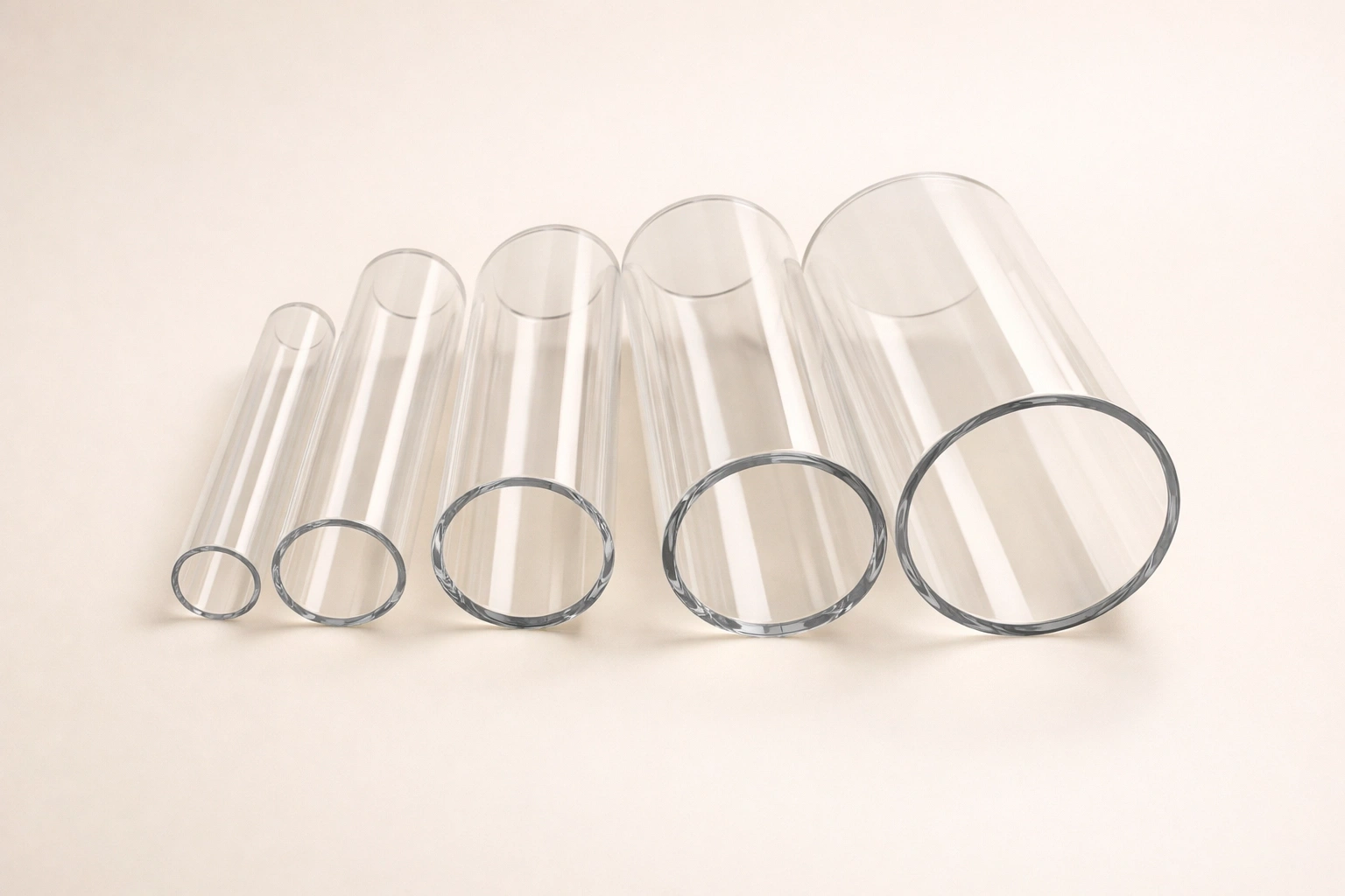
Dimensional coverage is the first filter every procurement engineer applies, and a supplier unable to meet the required outer diameter, wall thickness, or length at the required tolerance is effectively eliminated before technical evaluation begins. TOQUARTZ stocks and manufactures quartz glass tubes across the full industrial size spectrum, from sub-millimetre capillaries used in X-ray diffraction to large-bore process tubes used in solar cell diffusion furnaces. The four parameters — outer diameter (OD), inner diameter (ID), wall thickness (WT), and length — each carry their own coverage range and tolerance regime, and understanding all four together is the only way to confirm dimensional fit before submitting a custom order.
Outer Diameter Coverage from Capillary to Large-Bore Tubing
Quartz glass tubes are commercially available across three distinct diameter segments, each serving a structurally different set of applications and manufactured by different drawing or forming processes.
Bu capillary segment spans OD from 0.1 mm to approximately 5 mm. Tubes in this range are drawn with wall thicknesses as thin as 0.01 mm and are used predominantly in X-ray diffraction sample mounting, microfluidics, and optical fibre alignment sleeves. Dimensional tolerances for capillaries at 0.1 mm OD are ±0.05 mm, tightening to ±0.05 mm across the 0.1–0.9 mm range and widening slightly to ±0.25 mm for diameters at 1.5 mm and above within the capillary segment — figures consistent with published data from Hampton Research and Charles Supper Company, both of which stock over 60 capillary sizes for immediate shipment.
Bu standard industrial segment runs from OD 3 mm through OD 300 mm, covering the overwhelming majority of laboratory, semiconductor, lighting, and chemical processing applications. Robson Scientific lists clear fused quartz tubing from 3.0 mm to 150.0 mm OD in metre lengths; MICQstore lists standard stocked sizes including OD 25 × WT 2, OD 40 × WT 3, OD 50 × WT 3, OD 60 × WT 3, OD 80 × WT 3, OD 100 × WT 3, OD 120 × WT 4, and OD 150 × WT 5 — all at 1,000 mm length — alongside a continuous custom service to 600 mm OD. Wall thickness across this segment typically ranges from 0.7 mm to 10.0 mm, a specification confirmed by gauge-glass.net data showing OD 3–400 mm with WT 0.7–10.0 mm.
Bu large-bore segment covers OD 100 mm to OD 600 mm. Tubes in this range require centrifugal casting1 or hot-press forming rather than vertical drawing, and they are used in solar photovoltaic diffusion furnaces, large CVD reactors, and industrial UV systems. Standard stocking at this diameter is limited; however, TOQUARTZ and comparable manufacturers accept custom orders for large-bore tubes with lengths exceeding 1,000 mm.
Outer Diameter Segment Reference
| Diameter Segment | OD Range | Typical WT Range (mm) | Birincil Uygulamalar |
|---|---|---|---|
| Capillary | 0.1 mm – 5 mm | 0.01 – 0.5 | XRD, microfluidics, fibre optics |
| Small Industrial | 3 mm – 50 mm | 0.7 – 3.0 | Lab apparatus, UV lamps, sensors |
| Medium Industrial | 50 mm – 150 mm | 2.0 – 5.0 | Semiconductor furnace tubes, reactors |
| Large Industrial | 150 mm – 300 mm | 3.0 – 8.0 | CVD process tubes, solar diffusion |
| Large Bore | 300 mm – 600 mm | 5.0 – 10.0 | Industrial furnace liners, large UV systems |
Inner Diameter and Wall Thickness Specifications
The inner diameter of any quartz tube is a derived dimension — it is not independently specified by the manufacturer but calculated as ID = OD − 2 × WT. This means that ordering a tube requires specifying two of the three values (OD, ID, WT), with the third confirmed by calculation.
Standard wall tubes in the industrial segment typically carry wall thicknesses between 1.0 mm and 3.0 mm, offering the best balance between mechanical integrity and thermal mass. Thick-wall tubes with WT of 4.0 mm to 10.0 mm are used in high-pressure reactors and vacuum chambers where structural load-bearing is required in addition to thermal and chemical resistance. Thin-wall tubes, particularly those with WT below 1.5 mm, are selected for applications requiring rapid thermal response — such as halogen lamp envelopes and infrared heater sheaths — where minimising thermal mass reduces cycle time and energy consumption. Common stocked OD × WT × ID combinations include: OD 25 × WT 2 × ID 21 mm, OD 50 × WT 3 × ID 44 mm, OD 100 × WT 3 × ID 94 mm, and OD 150 × WT 5 × ID 140 mm.
For high-precision assembly applications such as semiconductor wafer carrier tubes, where quartz tubes must interface with machined metal flanges or PTFE seals, ID tolerances become the critical dimension and are held to ±0,1 mm on medium-bore tubes, with tighter grades available at ±0,05 mm through CNC centerless grinding.
Common OD × WT × ID Combinations
| Dış çap (mm) | WT (mm) | Kimlik (mm) | Wall Category |
|---|---|---|---|
| 12 | 1.0 | 10 | Thin wall |
| 25 | 2.0 | 21 | Standard wall |
| 40 | 3.0 | 34 | Standard wall |
| 50 | 3.0 | 44 | Standard wall |
| 80 | 3.0 | 74 | Standard wall |
| 100 | 3.0 | 94 | Standard wall |
| 120 | 4.0 | 112 | Thick wall |
| 150 | 5.0 | 140 | Thick wall |
| 200 | 6.0 | 188 | Thick wall |
| 300 | 8.0 | 284 | Heavy wall |
Standard and Custom Length Ranges
Length availability differs significantly between small-bore and large-bore tube inventory, and understanding the default stock lengths prevents costly assumptions during system design.
For tubes up to OD 50 mm × ID 44 mm (inclusive), the industry-standard stock length is 48 inches (approximately 1,220 mm). For larger diameters — particularly those above OD 50 mm ID × OD 54 mm — the standard stock length extends to 60 inches (approximately 1,524 mm), and minimum order quantities may apply. These figures align directly with GM Quartz's published stock specifications. Custom non-standard lengths are available across the full diameter range upon request.
Custom-cut lengths begin at 5 mm and extend to a maximum of 3,000 mm, a ceiling confirmed by both MICQstore and microqsil.com for fused quartz tubes. For most laboratory and semiconductor applications, lengths between 500 mm and 1,500 mm represent the practical working range. Tubes exceeding 2,000 mm in length at diameters above 100 mm are subject to individual engineering review due to deflection and handling constraints during shipping.
Cutting to non-standard lengths is performed as part of the fabrication service with a length tolerance of ±0,5 mm for standard precision cutting, or ±0,1 mm where laser or high-precision diamond-wheel cutting is specified.
Standard Stock and Custom Length Parameters
| Tube OD Range | Standard Stock Length | Maximum Custom Length | Length Tolerance (Standard Cut) |
|---|---|---|---|
| 0.1 mm – 5 mm (capillary) | 80 mm / 300 mm / 600 mm | 600 mm | ±0,05 mm |
| 3 mm – 50 mm | 1,220 mm (48 in) | 3,000 mm | ±0,5 mm |
| >50 mm – 300 mm | 1,524 mm (60 in) | 3,000 mm | ±0,5 mm |
| >300 mm – 600 mm | Custom per order | >1,000 mm (case by case) | ±1.0 mm |
Dimensional Tolerances and Precision Grades
Tolerance selection is arguably the most consequential specification decision after material grade, because tighter tolerances require additional machining steps that directly affect lead time and processing scope.
Published OD tolerances for fused quartz tubing follow a diameter-graduated scale. At the capillary end (OD 0.1–0.9 mm), the OD tolerance is ±0,05 mm; for diameters from 1.0 mm to 2.5 mm, it ranges from −0.05 mm to +0.25 mm depending on the specific size; and for diameters at 3.0 mm and above, the standard tolerance broadens to ±0,25 mm — data consistent with Hampton Research's published capillary specification table. For industrial tubes in the 25–150 mm OD range, as-drawn OD tolerances from the tube manufacturer are typically ±0.5 mm to ±1.0 mm, reflecting the inherent variability of the vertical drawing process.
Precision-ground tubes, where the outer or inner diameter has been finish-machined after drawing, can achieve OD and ID tolerances of ±0.0001 inch (approximately ±0.0025 mm) — a specification documented by Specialty Glass Products for CNC centerless-ground fused quartz tubing. At the most demanding level, CNC machining centres used in semiconductor-grade component production hold tolerances to ±0,01 mm across all linear dimensions. Length cut tolerance for standard diamond-wheel cutting is ±0,5 mm, reducible to ±0,1 mm with laser cutting. Wall thickness uniformity is typically controlled to ±10% of nominal WT for drawn tubes, tightening to ±0,05 mm for ground tubes.
Understanding which tolerance grade applies to a given assembly is essential before committing to a fabrication route, since specifying optical-grade tolerances on a component that only requires furnace tube fit clearance adds unnecessary cost and lead time.
Dimensional Tolerance Reference by Precision Grade
| Parametre | As-Drawn (Standard) | Hassas Zemin | CNC Machined |
|---|---|---|---|
| OD Toleransı | ±0.25 mm – ±1.0 mm | ±0.01 mm – ±0.025 mm | ±0,01 mm |
| ID Tolerance | ±0.25 mm – ±1.0 mm | ±0.05 mm – ±0.1 mm | ±0,01 mm |
| WT Uniformity | ±10% of nominal | ±0,05 mm | ±0,01 mm |
| Length (cut) | ±0,5 mm | ±0.1 mm (laser) | ±0,1 mm |
| Surface Ra (OD) | 0.4 – 1.6 µm | 0.1 – 0.4 µm | <0.1 µm |

Precision Fabrication for Quartz Glass Tubes — Cutting
Dimensional coverage alone rarely satisfies a procurement requirement; most applications demand tubes cut to a precise working length with edge conditions that will not introduce stress fractures or contamination during service. Cutting is the foundational step in the TOQUARTZ fabrication sequence, and the method selected — diamond-wheel wet cutting or laser cutting — determines the achievable length tolerance, edge profile, and whether subsequent edge treatment is required.
Diamond Wheel Wet Cutting for Small and Medium Bore Tubes
Wet diamond-wheel cutting is the industry-standard method for quartz tube lengths, applied across bore diameters from 3 mm OD up to approximately 150 mm OD with consistent, repeatable results.
The process uses a diamond-impregnated abrasive wheel rotating under continuous water coolant flow. The water serves a dual purpose: it suppresses the fine silica dust that would otherwise create an airborne health hazard, and — more critically from a product quality standpoint — it prevents localised thermal shock at the cut zone. Without coolant, the frictional heat generated by a dry diamond cut can introduce subsurface microcracks extending 0.05 mm to 0.2 mm into the tube wall, which propagate during subsequent thermal cycling in service. Wet cutting reduces this subsurface damage zone to below 0.02 mm, a depth that is fully removed by standard chamfering or fire polishing in the next fabrication step. Great Lakes Glasswerks documents wet-cutting capability across bores from 3 mm OD to 150 mm OD, using a proprietary fixturing process that maintains tube alignment and prevents wall deflection during the cut stroke.
The achievable length tolerance using wet diamond-wheel cutting is ±0,5 mm under standard production conditions, which satisfies the assembly requirements of most laboratory apparatus, furnace tube systems, and lamp envelope applications. For applications requiring tighter length control without laser investment, a secondary facing operation using a flat diamond lap can reduce length deviation to ±0,2 mm.
Diamond Wheel Cutting Parameters
| Parametre | Şartname |
|---|---|
| Applicable OD Range | 3 mm – 150 mm |
| Soğutma sıvısı | Continuous deionised water flood |
| Uzunluk Toleransı | ±0.5 mm (standard) |
| Subsurface Damage Depth | <0.02 mm with wet process |
| Wheel Grit (typical) | 150 – 320 mesh diamond |
| Post-Cut Edge Condition | Requires chamfer or fire polish |
Laser Cutting and Precision Length Tolerances
Laser cutting extends the achievable precision beyond what diamond-wheel processes can deliver and becomes the preferred method when length tolerances tighter than ±0.5 mm are specified, or when tube diameters exceed the mechanical constraints of wheel-based systems.
CO₂ laser cutting, operating at a wavelength of 10.6 µm, is absorbed efficiently by fused silica, enabling clean, narrow kerf cuts with a heat-affected zone measured in micrometres rather than the tenths-of-a-millimetre characteristic of mechanical methods. At typical processing speeds for quartz tubes in the 10–80 mm OD range, the laser kerf width is 0.1 to 0.3 mm, and the length tolerance achieved is ±0,1 mm — a fivefold improvement over standard wet cutting. Crucially, the absence of mechanical contact eliminates the risk of tube cracking from wheel vibration, making laser cutting particularly valuable for thin-wall tubes with WT below 1.5 mm where mechanical cutting force presents a fracture risk.
For large-diameter tubes above 150 mm OD, waterjet cutting provides an alternative route, combining abrasive jet energy with a process that generates no thermal stress at all. Waterjet-cut edges require grinding to remove the roughened surface left by the abrasive medium, but the method is uniquely capable of producing complex contoured profiles — diagonal cuts, notches, or slotted ends — in large-bore quartz tubing that would otherwise require multi-axis CNC machining.
Laser vs Diamond-Wheel Cutting Comparison
| Öznitelik | Diamond Wheel Wet Cut | Laser Cut | Waterjet Cut |
|---|---|---|---|
| OD Range | 3 mm – 150 mm | 5 mm – 200 mm | 50 mm – 600 mm |
| Uzunluk Toleransı | ±0,5 mm | ±0,1 mm | ±0.3 mm |
| Kerf Width | 0.5 – 1.5 mm | 0.1 – 0.3 mm | 1.0 – 2.5 mm |
| Thermal Stress Risk | Low (wet process) | Çok düşük | Hiçbiri |
| Edge Post-Treatment | Chamfer/fire polish | Light fire polish | Grinding required |
| En İyi Uygulama | Standard lab/industrial lengths | Precision components | Large-bore contoured cuts |
Chamfering and Edge Treatment on Quartz Glass Tubes
Every cut end of a quartz glass tube presents a mechanically vulnerable condition: the sharp 90° corner left by diamond-wheel or laser cutting concentrates stress when the tube is inserted into fittings, subjected to thermal cycling, or handled during installation. Chamfering removes this vulnerability while simultaneously producing the controlled edge geometry that sealing assemblies, O-ring grooves, and push-fit connectors depend upon.
Mechanical Grinding and Typical Chamfer Angles
Mechanical chamfering uses diamond-impregnated grinding wheels or precision cylindrical grinders to abrade the tube end to a defined angular profile, producing a consistent, repeatable geometry across production batches.
Chamfer angles between 15° and 45° (measured from the tube axis) are the most commonly applied range for quartz tube ends. A 15°–20° chamfer is typically specified for tubes that will be inserted into PTFE or silicone O-ring seals, where the gentle taper guides the tube end into the seal bore without cutting the elastomer. A 45° chamfer is preferred for tubes that will be flame-sealed or fusion-welded in a subsequent step, since the angled face provides a larger surface area for the torch flame to heat uniformly, reducing the risk of asymmetric softening. Grinding equipment for OD chamfering uses an OD cylindrical grinder that rotates the tube against a profiled diamond wheel; ID chamfering of tubes above 10 mm ID is performed with a mounted point grinder running inside the bore at the specified angle. Specialty Glass Products documents OD grinding capability achieving OD tolerances of ±0.0001 inch (±0.0025 mm) with exceptional surface finish, illustrating that chamfering on precision-grade tubes is a machining operation in the metrology sense, not merely a finishing touch.
Post-grinding, the chamfered surface exhibits a matte, frosted appearance. For applications where the end face must transmit UV or visible light — such as the input end of a UV reactor tube — the frosted chamfer surface is subsequently fire-polished to restore optical transparency.
Chamfer Angle and Application Reference
| Chamfer Angle | Geometri | Tipik Uygulama |
|---|---|---|
| 15° – 20° | Gentle taper | O-ring and elastomer seal insertion |
| 30° | Moderate taper | Push-fit connectors, compression fittings |
| 45° | Standard bevel | Pre-weld face prep, general deburring |
| Özel | Per drawing | Vacuum flanges, optical interfaces |
Acid-Etching Deburring as a Complementary Option
For quartz glass tubes with inner diameters below 10 mm, mechanical grinding tools cannot physically access the bore end with sufficient precision, making acid-etching the practical deburring route.
Dilute hydrofluoric acid (HF), typically at concentrations of 1–5% by volume, selectively dissolves the sharp silica slivers and microfractures left at the cut edge without altering the macroscopic tube geometry. The etch rate of fused quartz in dilute HF at room temperature is approximately 0.5–2 µm per minute, allowing controlled material removal to be stopped once the burr zone — typically 10–30 µm deep — has been consumed. This precision of control makes HF etching particularly valuable for capillary tubes with OD of 0.5–5 mm, where even a 50 µm mechanical grinding overstep would consume a significant fraction of the wall thickness. The process must be conducted in an HF-rated chemical fume hood with full PPE including face shield, chemical-resistant gloves, and an HF antidote kit on hand, as HF is systemically toxic even at low exposure levels.
Following the etch step, the tube is thoroughly rinsed in deionised water and optionally followed by a dilute ammonium bifluoride neutralisation wash. The resulting inner edge is smooth to the touch, with no residual crystalline silica particulate that would contaminate semiconductor or analytical chemistry flows.
Acid-Etching Deburring Parameters
| Parametre | Şartname |
|---|---|
| Applicable ID Range | 0.1 mm – 10 mm (inner edge access) |
| HF Concentration | 1 – 5% v/v |
| Etch Rate | 0.5 – 2 µm/min at 20°C |
| Material Removal Depth | 10 – 50 µm (controlled) |
| Post-Etch Rinse | Deionised water, ≥3 cycles |
| Dimensional Impact | Negligible (<0.05 mm change on OD) |

Polishing Standards for Quartz Glass Tubes in Optical and Semiconductor Use
The surface condition of a quartz tube end face is not merely an aesthetic concern — in optical transmission, UV reactor, and semiconductor diffusion applications, surface roughness at the tube end directly determines transmission efficiency, particle generation risk, and the quality of hermetic seals. Two polishing routes serve distinct requirements: fire polishing restores the smooth, fire-formed surface to cut ends, while mechanical lapping and polishing achieves optical-grade flatness for precision component interfaces.
Fire Polishing for End Faces and Tube Exteriors
Fire polishing is the most widely employed finishing operation for quartz tube end faces, valued for its speed, its ability to heal microcracks introduced during cutting, and its capacity to restore the pristine fire-formed surface quality of the original drawn tube.
The process applies a focused oxy-hydrogen or oxy-propane flame to the tube end while the tube is rotated about its axis. The flame temperature at the working tip exceeds 1,700°C, which is above the softening point of fused quartz (~1,665°C) but is applied for a controlled duration — typically 3 to 15 seconds per end — sufficient to remelt and flow the surface silica without collapsing the tube wall or significantly altering the tube OD. During this brief molten interval, surface tension2 drives the liquid silica into a smooth, near-perfectly flat end face, simultaneously sealing any subsurface microcracks left by mechanical cutting. GlobalQT explicitly lists fire polishing as a standard service alongside rough cutting and grinding for ordered furnace tubes, confirming its status as a production-grade process rather than a specialist one-off operation.
Oxy-hydrogen is strongly preferred over oxy-propane for high-purity semiconductor and optical applications, because hydrogen combustion produces only water vapour as a byproduct — leaving no carbon deposits on the silica surface. An oxy-propane flame, while hotter and therefore faster, introduces trace hydrocarbon contamination that fluoresces under UV illumination and is unacceptable in applications such as UV water treatment reactors or spectroscopic cells.
Fire Polishing Process Parameters
| Parametre | Oxy-Hydrogen | Oxy-Propane |
|---|---|---|
| Flame Temperature | ~2,000°C (working tip) | ~1,900°C |
| Combustion Byproduct | H₂O only | CO₂ + H₂O + trace carbon |
| Kirlenme Riski | İhmal edilebilir | Low (acceptable for industrial use) |
| Applicable OD Range | 1 mm – 300 mm | 3 mm – 300 mm |
| Processing Time per End | 3 – 15 sec | 2 – 10 sec |
| Microcrack Healing Depth | Up to 0.2 mm | Up to 0.2 mm |
| Surface Ra after Polish | 0.05 – 0.2 µm | 0.1 – 0.4 µm |
Mechanical Lapping and Optical-Grade Surface Finishes
Where fire polishing produces a smooth but geometrically free-formed surface — meaning the end face is not guaranteed to be flat or perpendicular to the tube axis — mechanical lapping produces a dimensionally controlled flat surface with optical-grade smoothness for applications demanding interferometric precision.
The mechanical polishing sequence for fused quartz tube ends begins with rough lapping using boron carbide or silicon carbide abrasive slurry on a cast iron lap plate, removing the bulk of the cut surface damage down to a residual surface roughness of approximately Ra 0.5 µm. The intermediate fine-lapping stage uses alumina abrasive (Al₂O₃) at 3–5 µm particle size, bringing the surface to Ra 0.1–0.2 µm. The final polishing stage employs cerium oxide (CeO₂) slurry on a polishing pad — typically a polyurethane or pitch lap — and achieves surface roughness values of Ra < 0.5 nm (sub-nanometre), classifying the result as optical grade per standard surface finish designations. At this level, the end face of the quartz tube is suitable as an optical window, a laser beam entry port, or a precision vacuum flange contact surface. Specialty Glass Products confirms CNC centerless grinding and polishing achieves OD and ID tolerances of ±0.0001 inch with exceptional surface finishes, illustrating that the polishing step is inseparable from dimensional control at optical-grade specifications.
Parallelism between the two end faces of a polished tube — critical for tubes used as flow cells or optical cuvettes — is maintained to ≤0.005 mm using a double-sided polishing machine with real-time laser micrometer feedback.
Polishing Grade and Surface Finish Reference
| Polishing Grade | Abrasive Used | Surface Ra | Tipik Uygulama |
|---|---|---|---|
| Industrial (fire polished) | Flame | 0.05 – 0.4 µm | Lab apparatus, furnace tubes, UV lamps |
| Semi-precision (lapped) | Al₂O₃ 3–5 µm | 0.1 – 0.5 µm | Sealing flanges, sensor interfaces |
| Optical grade (CeO₂) | CeO₂ slurry | <0.5 nm (Ra) | UV windows, spectroscopy cells, laser ports |
| Ultra-precision | CeO₂ + pitch lap | <0.1 nm (Ra) | Interferometry, laser beam shaping |
Flame Sealing and End Closure Options for Quartz Glass Tubes
Sealed-end quartz tubes appear across dozens of applications — from UV mercury lamp envelopes and thermowell protection tubes to vacuum ampoules for crystal growth and sealed reaction vessels for inorganic synthesis at temperatures above 1,000°C. The method and geometry of end closure are not interchangeable: the combination of heat source, flame chemistry, and forming technique must be matched precisely to the tube diameter, wall thickness, and the end profile geometry required by the application.
Oxy-Hydrogen Torch Welding for Hermetic End Seals
Flame sealing of quartz glass tubes requires a heat source capable of reaching and sustaining the softening temperature of fused silica — approximately 1,665°C — while keeping the surrounding tube section cool enough to prevent deformation beyond the intended seal zone.
Oxy-hydrogen torches are universally preferred for hermetic quartz sealing because the hydrogen/oxygen flame reaches working temperatures of 1,800–2,000°C at the flame tip, and because — as established in documented glass-blowing practice across semiconductor and scientific glass communities — the flame produces no carbon byproducts that would contaminate the silica melt zone. When the tube end reaches the working temperature, it behaves more like a molten metal at its liquidus point than a gradually softening glass: the transition from rigid to fully workable is abrupt, requiring the operator to manage heat application with precision. The tube must be rotated continuously during heating to achieve a symmetric melt pool; asymmetric heating causes the wall to collapse unevenly, producing a seal with internal stress concentrations that fail under thermal cycling. After sealing, the sealed tube section is slowly cooled in the torch's reducing outer flame zone to anneal residual stress before full air quench. Properly executed, an oxy-hydrogen flame seal on fused quartz is helium-leak tested to <1 × 10⁻⁹ mbar·L/s, confirming hermetic vacuum-grade integrity.
The maximum OD for flame sealing in standard production is approximately 100 mm; above this diameter, the thermal mass of the tube requires a multi-burner approach or a furnace-assisted sealing process.
Flame Sealing Process Parameters
| Parametre | Şartname |
|---|---|
| Heat Source | Oxy-hydrogen torch |
| Flame Tip Temperature | 1,800 – 2,000°C |
| SiO₂ Softening Point | ~1,665°C |
| Applicable OD Range | 1 mm – 100 mm |
| Post-Seal Annealing | Required (torch-zone cooling) |
| Leak Integrity | <1 × 10⁻⁹ mbar·L/s (He leak test) |
| Byproduct Contamination | None (H₂O only) |
Round-Bottom and Flat-Bottom Closed-End Configurations
The geometry of a closed end is not merely aesthetic — it determines pressure distribution, cleaning accessibility, and whether the tube can stand upright without an external support fixture.
Round-bottom (hemispherical) closed ends are formed by accumulating the softened silica at the tube terminus into a dome under surface tension, without added material. The resulting shape distributes internal pressure uniformly across the curved surface, making round-bottom closures the preferred geometry for sealed ampoules, high-pressure reaction tubes, and thermocouple protection wells operating under both positive and negative (vacuum) pressure. The wall thickness at the dome apex is typically 80–110% of the original tube wall thickness, since the surface tension forming process can cause slight thinning or thickening depending on flame dwell time. Round-bottom tubes are not self-standing on a flat surface without a support rack, which must be factored into laboratory setup design.
Flat-bottom closed ends are produced by collapsing the tube end in a flat-faced mandrel press while the silica is in the plastic state, or by flame-sealing against a flat fused quartz plate. The result is a tube that stands vertically unsupported — a practical advantage in tube furnaces where quartz boats and sample tubes must rest on flat furnace floors. However, flat closures are mechanically less resistant to uniform internal pressure than hemispherical closures, and their use under pressures above 0.3 MPa (gauge) requires engineering review.
Closed-End Geometry Comparison
| Öznitelik | Round-Bottom | Flat-Bottom |
|---|---|---|
| Forming Method | Surface tension (flame only) | Mandrel press + flame |
| Pressure Distribution | Uniform (optimal) | Stress concentration at corners |
| Max Recommended Internal Pressure | Up to 1.0 MPa (gauge) | Up to 0.3 MPa (gauge) |
| Self-Standing | No (requires support) | Evet |
| Tipik Uygulamalar | Ampoules, thermowells, reaction vessels | Furnace tube inserts, sample boats |
| Apex Wall Thickness | 80 – 110% of nominal WT | 90 – 120% of nominal WT |

Drilling and Aperture Machining through Quartz Glass Tubes
Drilled apertures in quartz glass tubes enable thermocouple insertion ports, gas inlet/outlet connections, sampling ports, and optical fibre feed-throughs — functions that cannot be achieved by any tube end processing operation. Unlike metals, fused quartz cannot be drilled by conventional twist drills; its hardness of approximately Mohs 7 and brittle fracture behaviour demand specialised drilling methods that remove material by controlled abrasion rather than plastic cutting.
Ultrasonic Drilling for Small-Diameter Holes
Ultrasonic drilling is the method of choice for holes in fused quartz where the aperture diameter falls below approximately 5 mm and wall thickness is 5 mm or less.
The process operates by vibrating a tungsten carbide or boron carbide tool tip at ultrasonic frequency (typically 20–40 kHz) with an amplitude of 10–50 µm, while a slurry of abrasive particles (typically boron carbide B₄C or silicon carbide SiC in water) floods the work zone. The vibrating tool hammers the abrasive particles against the quartz surface in a percussive action that removes material at approximately 0.1–0.5 mm per minute without transmitting significant lateral force to the tube wall — the critical advantage over rotary drilling for fragile thin-wall tubes. Documented minimum hole diameters achievable by ultrasonic drilling in fused quartz are 0.8 mm, as confirmed by micquartz.com's published CNC machining data. Positional tolerance for ultrasonically drilled holes is typically ±0,05 mm, with diameter tolerance ±0.02 mm — figures that satisfy the alignment requirements of thermocouple sheaths and capillary insert fittings.
Following ultrasonic drilling, the hole entrance and exit require chamfering — either mechanical or acid-etch — to eliminate the 0.05–0.1 mm rim fracture zone that forms when the abrasive tool breaks through the exit face of the quartz wall.
Ultrasonic Drilling Parameters
| Parametre | Şartname |
|---|---|
| Minimum Hole Diameter | 0.8 mm |
| Maximum Hole Diameter | ~5 mm |
| Frekans | 20 – 40 kHz |
| Tool Amplitude | 10 – 50 µm |
| Abrasive Medium | B₄C or SiC slurry in water |
| Malzeme Kaldırma Oranı | 0.1 – 0.5 mm/min |
| Çap Toleransı | ±0.02 mm |
| Positional Tolerance | ±0,05 mm |
CNC Diamond Drilling for Larger Apertures and Tight Tolerances
For aperture diameters above 5 mm, CNC diamond core drilling replaces ultrasonic methods, offering higher dimensional accuracy, faster cycle times, and the ability to produce holes in tubes up to 300 mm OD where the tube wall thickness provides sufficient material for core drill engagement.
CNC diamond core drilling uses hollow diamond-impregnated core drill bits rotating under continuous deionised water coolant, removing a cylindrical plug of fused quartz from the tube wall. At a spindle speed of 300–1,500 RPM and an infeed rate of 0.02–0.1 mm per revolution, the heat generated at the cutting face is dissipated into the coolant before it can initiate thermal microcracking. Specialty Glass Products documents the ability to drill holes down to 0.017 inches (0.43 mm) in fused quartz using this approach, with multi-axis milling centres handling tube diameters up to the machine's envelope — typically 300 mm diameter and up to 750 mm in length on a 5-axis CNC. Diameter tolerance for CNC-drilled holes in the 5–50 mm range is ±0.02 mm, consistent with published data from micquartz.com. For holes requiring greater positional accuracy in gas manifold or multi-port reactor designs, CNC toolpath programming achieves positional tolerance of ±0.01 mm relative to the tube axis.
Post-drilling, every aperture receives a standard 45° chamfer at both entry and exit faces to eliminate stress concentration — a step explicitly recommended in quartz machining literature to prevent crack propagation under thermal load.
CNC Diamond Drilling Parameters
| Parametre | Şartname |
|---|---|
| Minimum Hole Diameter | 0.43 mm (0.017 in) |
| Maximum Hole Diameter | Limited by wall thickness (typically ≤ OD × 0.6) |
| Spindle Speed | 300 – 1,500 RPM |
| Infeed Rate | 0.02 – 0.1 mm/rev |
| Soğutma sıvısı | Continuous deionised water |
| Çap Toleransı | ±0.02 mm |
| Positional Tolerance | ±0,01 mm |
| Post-Drill Edge Treatment | 45° chamfer (mandatory) |
Ground Joints and Frosted-Mouth Processing on Quartz Glass Tubes
Laboratory and industrial systems built from quartz components depend on standardised interconnections to achieve gas-tight or vacuum-tight assemblies without adhesive or mechanical fasteners. Ground joints — precision-machined conical, spherical, or flat-flanged interfaces — allow quartz glass tubes to connect interchangeably with other quartz, borosilicate, or glass-ceramic apparatus across a globally standardised size system, providing airtight seals when properly mated and greased.
Standard Taper Joints — Size Notation and Precision Grinding
The standard taper ground joint is described by a two-number notation in the form XX/YY, where XX is the outer diameter of the narrow end of the male (inner) joint in millimetres, and YY is the length of the ground surface in millimetres.
Common standard sizes include 14/20, 19/22, and 24/40, which correspond to the ASTM E-676 American standard taper joints and the ISO 383 / DIN 12242 European standard. The taper ratio for all standard joints is 1:10 — for every 10 mm of joint length, the diameter increases by 1 mm — a geometry that has been internationally standardised to ensure that any two joints sharing the same XX designation will mate regardless of manufacturer. Fabrication of a quartz taper joint follows a two-stage grinding sequence: rough grinding using silicon carbide or diamond abrasive removes the bulk of tube-wall material to shape the cone, and fine grinding with finer abrasive brings the surface to a frosted (matte) finish that forms a gas-tight seal when paired with its socket counterpart and lubricated with an appropriate grease such as Apiezon or silicone stopcock grease. The frosted surface provides physical interlock between mating faces through microscopic asperity engagement; a clear, polished taper joint would be gas-permeable. DWK Life Sciences documents that their two-stage grinding process produces joints that surpass the ISO 383 and DIN 12242 accuracy requirements, with surface quality sufficient for both atmospheric and vacuum-tight sealing.
The resulting joint, when properly assembled and greased, is gas-tight at atmospheric pressure and vacuum-tight to better than 10⁻³ mbar with standard silicone grease, extendable to 10⁻⁶ mbar with Apiezon H or M high-vacuum grease.
Standard Taper Joint Size Reference
| Size Designation | Top Diameter (mm) | Joint Length (mm) | Compatible Standard | Tipik Uygulama |
|---|---|---|---|---|
| 10/19 | 10 | 19 | ISO 383 | Micro-scale lab apparatus |
| 14/20 | 14 | 20 | ASTM E-676 | Standard lab glassware |
| 14/23 | 14 | 23 | ISO 383 | Standard lab glassware (EU) |
| 19/22 | 19 | 22 | ASTM E-676 | Medium-scale apparatus |
| 24/29 | 24 | 29 | ISO 383 | Medium-scale apparatus (EU) |
| 24/40 | 24 | 40 | ASTM E-676 | Reaction flasks, distillation |
| 29/32 | 29 | 32 | ISO 383 | Large-scale apparatus |
| 45/50 | 45 | 50 | Custom / industrial | Industrial-scale reactors |
Ball-and-Socket and Flat-Flange Ground Joint Variants
Standard taper joints require precise axial alignment between mating components; even a few degrees of angular misalignment concentrates stress at the joint neck, risking fracture during assembly or thermal cycling. Ball-and-socket joints and flat-flange ground joints address this limitation through geometric variants that tolerate angular deviation or distribute sealing load across a flat face.
Ball-and-socket joints (also called spherical ground joints) consist of a precisely ground spherical male ball component and a matching concave female socket, manufactured in standard 'S' sizes: S13, S19, and S29, where the number denotes the nominal bore diameter in millimetres. The spherical geometry allows up to ±10° of angular misalignment without compromising seal integrity, making these joints indispensable in complex multi-port reactor assemblies where thermal expansion causes component axes to shift relative to one another during heat-up cycles. The mating surfaces of both ball and socket are precision-ground to the same frosted finish used in taper joints, and sealing performance under vacuum matches that of taper joints when proper clamping force is applied. Aoxin Quartz confirms stock availability in S13, S19, and S29 sizes fabricated from high-purity fused quartz, with fusion attachment to tube shanks as part of the standard product offering.
Flat-flange ground joints present a flat, planar sealing face produced by precision lapping, used in vacuum chambers and reactor vessels where the tube must mate with a machined metal or quartz flange. The flat face is lapped to a surface roughness of Ra 0.1–0.5 µm and a flatness of ≤0.01 mm across the flange face, enabling metal-to-quartz seals with compressed elastomeric or PTFE gaskets. This joint type is particularly common in semiconductor diffusion tube end caps and photochemical reactor flanges operating under vacuum at temperatures up to 600°C.
Ground Joint Type Comparison
| Joint Type | Angular Tolerance | Standard Sizes | Seal Grade | Tipik Uygulama |
|---|---|---|---|---|
| Standard Taper | 0° (axial only) | 14/20, 19/22, 24/40, 24/29, 29/32 | Atm. to 10⁻⁶ mbar | Lab glassware, distillation, synthesis |
| Ball-and-Socket | ±10° angular flex | S13, S19, S29 | Atm. to 10⁻⁴ mbar | Complex assemblies, thermal expansion |
| Flat Flange | N/A (planar) | Custom per OD | Atm. to 10⁻⁶ mbar | Vacuum chambers, semiconductor flanges |
| O-Ring Flange | N/A | Custom per bore | Atm. to 10⁻⁸ mbar | Ultra-high vacuum, clean room |
Welding, Tube Expansion and Diameter Reduction for Quartz Glass Tubes
Beyond single-piece fabrication, many engineering applications require quartz glass tubes to be joined into multi-section assemblies, fitted with flanges, or formed with changing diameters along their length — functions that require thermal forming rather than machining. Welding, tube expansion (flaring), and diameter reduction (necking) are the three primary hot-forming operations applied to quartz glass tubes, and each demands precise control of flame temperature, glass viscosity, and post-forming annealing3 to produce joints and transitions free of residual stress.
Oxy-Hydrogen Fusion Welding for Tube-to-Tube and Flange Joints
Quartz-to-quartz fusion welding is distinct from the welding of metals in one fundamental respect: there is no filler material, no electrode, and no external shielding gas. The joint is formed entirely by softening both mating surfaces simultaneously with a high-temperature flame until they flow together at the molecular level.
Oxy-hydrogen torch welding is the mandated method for any quartz joint intended for semiconductor, pharmaceutical, or optical service, because the combustion produces exclusively water vapour — leaving the silica melt zone chemically pristine and free of the carbon, hydroxide contamination, or alkali deposits that would compromise purity. The fused quartz must be heated uniformly to its working temperature of approximately 1,800°C, rotating continuously on a glass lathe or multi-axis positioner to prevent asymmetric flow. The joint must achieve intimate molecular contact across 100% of the mating face area; any gap, bubble, or partially un-fused zone creates a stress riser that will initiate fracture during the first thermal cycle. After fusion, the joint zone is held in the torch's outer flame — a cooler reducing zone at approximately 800–1,000°C — for a controlled anneal period of 30 to 90 seconds per millimetre of wall thickness, before gradual air cooling. This annealing step is non-negotiable: quartz has essentially zero thermal expansion, meaning that rapid cooling generates no macroscopic dimensional change, but the residual viscous stress frozen into an un-annealed weld zone is sufficient to cause spontaneous fracture days or weeks after fabrication. Community documentation from both professional glass blowers and semiconductor physicists consistently emphasises that oxy-hydrogen is the only acceptable heat source for clean quartz welding, and that quartz does not require post-fusing normalisation comparable to standard glass precisely because its CTE is effectively zero.
Flange-to-tube welding follows the same process but requires the flange component to be pre-heated to near working temperature before contact to prevent thermal shock fracture at the moment of junction. Axquartz.com and fgquartz.com both list welding as a standard custom fabrication capability, with ISO 9001:2015 certification governing the process.
Fusion Welding Process Parameters
| Parametre | Şartname |
|---|---|
| Heat Source | Oxy-hydrogen torch only (production grade) |
| Çalışma Sıcaklığı | ~1,800°C at joint face |
| Applicable OD Range | 3 mm – 200 mm (standard); >200 mm multi-burner |
| Annealing Duration | 30 – 90 sec per mm of WT |
| Coolant / Shielding Gas | None required |
| Joint Purity | No filler; 100% fused silica |
| Leak Integrity (post-weld) | <1 × 10⁻⁹ mbar·L/s (He leak test capable) |
| Maximum Material Purity | Up to 99.999% SiO₂ (matched to tube grade) |
Tube Expansion and Neck-Down Diameter Forming
Diameter transitions — where a tube section expands to a larger OD to mate with a wide-bore flange, or reduces to a smaller OD to create a nozzle or transition fitting — are produced by heating the forming zone to the plastic state and applying controlled mechanical force against a mandrel, die, or by exploiting internal pressure (blowing).
Tube expansion (flaring) begins with the local zone of the tube being heated to approximately 1,700–1,800°C over a length equal to approximately 1.5–2× the target flared OD. Once fully plastic, a conical graphite mandrel is inserted and pressed into the tube end, expanding the diameter outward. The resulting OD at the expanded end is typically 1.3× to 2.0× the original tube OD, with wall thickness decreasing proportionally by the inverse square of the diameter ratio — a tube with original WT of 3 mm expanded by a factor of 1.5 in OD will have a wall thickness at the expanded end of approximately 1.3 mm (calculated from volume conservation). Flared ends are used to create ball-joint entry flanges, large-diameter sealing lips for O-ring compression, and transition sections between different tube diameters in multi-stage UV reactor designs. The flare angle — typically 10° to 30° half-angle — is determined by the mandrel profile and must be matched to the mating component drawing.
Diameter reduction (necking) applies compression to the heated zone using a rotating graphite paddle or a profiled die, reducing the OD at the tube end to create a reduced-bore nozzle, a stepped transition, or a constriction for flow metering. Wall thickness at the necked zone increases as OD decreases, following material conservation: a tube necked from OD 50 mm to OD 30 mm with original WT 3 mm will have a wall thickness at the neck of approximately 8.3 mm, which may require consideration in thermal design. Both expansion and reduction operations are followed by annealing, and both are available as custom fabrication services at TOQUARTZ for tube diameters in the range of 5 mm to 200 mm OD.
Diameter Forming Parameters
| Parametre | Expansion (Flaring) | Reduction (Necking) |
|---|---|---|
| Applicable OD Range | 5 mm – 200 mm | 5 mm – 200 mm |
| Heating Temperature | 1,700 – 1,800°C | 1,700 – 1,800°C |
| Forming Tool | Graphite conical mandrel | Graphite paddle / profiled die |
| Typical Diameter Change Ratio | 1.3× – 2.0× OD increase | 0.3× – 0.8× OD reduction |
| Wall Thickness at Formed End | Decreases (OD increase) | Increases (OD decrease) |
| Flare / Transition Half-Angle | 10° – 30° | 5° – 20° |
| Post-Forming Annealing | Zorunlu | Zorunlu |
| OD Tolerance at Formed End | ±1.0 mm (standard) | ±0.5 mm (standard) |

Industries That Rely on Precisely Fabricated Quartz Tubing
Fabricated quartz tubing serves as an enabling component rather than a commodity consumable in the industries below — its presence is invisible when functioning correctly, and its failure is immediately consequential.
-
Semiconductor Diffusion and CVD: Quartz glass tubes are the primary process tubes in horizontal and vertical diffusion furnaces for silicon wafer oxidation, doping, and chemical vapour deposition. Operating continuously at 900–1,200°C with process gases including O₂, N₂, HCl, and dichlorosilane, these tubes must maintain 99,99'un üzerinde SiO₂ saflığı5% to prevent metallic contamination of wafers at the sub-ppb level. Tube diameters range from OD 100 mm (4-inch wafer generation) to OD 300 mm and above (12-inch and advanced nodes). Precision-machined flat flanges and welded end caps are standard specifications for this application. The specification for semiconductor-grade process tubes is often held to OD tolerance of ±0.1 mm and surface finish requirements that exclude any abrasive contamination.
-
UV Disinfection and Water Treatment: Quartz glass tubes serve as the outer protective sleeve and the UV-transmitting window between mercury vapour lamps and the water flow stream in UV reactor systems. Low-OH, high-transmission quartz — typically JGS1 or synthetic fused silica — is required, with UV transmittance above 90% at 254 nm to ensure germicidal efficacy. Outer diameters in this application typically range from OD 22 mm to OD 45 mm, with lengths from 500 mm to 1,500 mm.
-
Infrared and Halogen Lamp Envelopes: Thin-wall quartz tubes with OD 6–16 mm and WT 0.7–1.5 mm form the envelopes of halogen lamps, infrared emitter tubes, and quartz-tungsten-halogen (QTH) sources. Fire-polished and sealed ends are standard; the tube must withstand repeated thermal shock from cold start to operating temperature (above 500°C filament zone) without fracture.
-
Solar Photovoltaic Diffusion Furnaces: Large-diameter quartz tubes (OD 150–300 mm, length up to 1,800 mm) are used as process chambers for phosphorus and boron diffusion in solar cell production. High thermal mass and extended length at large OD are the critical dimensional requirements for this segment.
-
Chemical and Pharmaceutical Processing: Quartz tube reactors, flow cells, and sight glasses in corrosive chemical processes benefit from quartz's resistance to all acids except HF. Welded flange assemblies and ground-joint connections to borosilicate apparatus via graded seals are standard in this sector.
-
Analytical Instrumentation: ICP-OES and ICP-MS plasma torches use precision quartz tubes with tightly controlled OD and concentricity — typically OD 18–22 mm outer torch tube, OD 15–18 mm intermediate tube — where dimensional variation directly affects plasma stability and analytical precision.
Material Grades for Quartz Glass Tubes — JGS1, JGS2 and JGS3
Selecting the correct material grade is the final specification parameter that determines whether a quartz tube will perform as expected in its optical, thermal, or purity environment, and the three standard Chinese national grades — JGS1, JGS2, and JGS3 — represent distinct points in the OH content / transmission / temperature-resistance trade-off space.
-
JGS1 is synthetic fused silica produced from chemical vapour deposition of silicon tetrachloride (SiCl₄). Its defining characteristic is an OH (hydroxyl) content below 1 ppm, which prevents the ~2.7 µm OH absorption band from attenuating infrared transmission and simultaneously maximises UV transmission down to approximately 150 nm. JGS1 is the specified grade for UV spectroscopy cells, excimer laser beam delivery, UV water treatment sleeves, and any application where transmission below 250 nm is critical. Its thermal deformation temperature exceeds 1,650°C, and it is the only JGS grade suitable for continuous service above 1,200°C without devitrification.
-
JGS2 is natural fused quartz produced by electric arc fusion of high-purity natural quartz crystals. OH content is higher than JGS1 — typically 150–400 ppm — which shifts UV transmission cutoff to approximately 250 nm, making JGS2 unsuitable for deep UV applications but entirely appropriate for visible and near-UV work (300–400 nm range). JGS2 is the dominant grade for semiconductor diffusion furnace tubes, chemical reactor tubes, and high-temperature laboratory apparatus where UV transmission is not a requirement. Its lower production cost relative to JGS1 makes it the rational default choice for thermal applications.
-
JGS3 is produced from natural quartz with higher natural mineral impurity and OH content — typically >400 ppm OH — and its UV transmission is limited to wavelengths above approximately 350 nm. JGS3 trades optical performance for structural robustness and cost efficiency, and it is widely used in halogen lamp envelopes, infrared heater tubes, and industrial furnace liners where only visible and IR transmission is relevant. Its continuous service temperature is approximately 1,100°C — lower than JGS1 and JGS2 at their respective maximums — due to trace impurity effects on devitrification kinetics.
Material Grade Selection Reference
| Mülkiyet | JGS1 | JGS2 | JGS3 |
|---|---|---|---|
| Üretim Yöntemi | CVD (SiCl₄ vapour) | Electric arc (natural quartz) | Electric arc (natural quartz) |
| OH İçerik | <1 ppm | 150 – 400 ppm | >400 ppm |
| UV Transmission Cutoff | ~150 nm | ~250 nm | ~350 nm |
| Transmission at 254 nm | >90% | 40 – 80% | <20% |
| Continuous Service Temp. (°C) | 1,250 | 1,200 | 1,100 |
| Devitrifikasyon Riski | Çok düşük | Düşük | Orta düzeyde |
| Tipik Uygulamalar | UV optics, excimer laser, spectroscopy | Semiconductor furnaces, chemical reactors | Halogen lamps, IR heaters, industrial furnaces |
| Relative Production Cost | En yüksek | Orta düzeyde | En düşük |
Request a Custom Specification for Your Quartz Glass Tubes Project
Across every dimensional segment and fabrication capability described in this article, TOQUARTZ accepts custom orders with no minimum order quantity on most tube sizes, and engineering feasibility assessments are returned within 24 hours of drawing submission.
Submitting a complete specification at first contact eliminates back-and-forth and accelerates quotation. The parameters required to generate an accurate quotation for custom quartz glass tubes are:
- OD × ID × WT (mm): Specify two of the three; the third is calculated.
- Length (mm): Specify required length and acceptable tolerance (±0.5 mm standard; ±0.1 mm laser cut).
- Material grade: JGS1, JGS2, or JGS3 (default JGS2 if not specified).
- Fabrication operations: From the complete list — cutting, chamfering, fire polishing, mechanical polishing, flame sealing (round/flat bottom), drilling (specify hole diameter and position), ground joint (specify size notation), welding, expansion, or reduction.
- End-use environment: Maximum service temperature, chemical exposure, UV transmission requirement, and vacuum/pressure level, where applicable.
- Quantity: Unit quantity and batch frequency if recurring orders are anticipated.
Sonuç
TOQUARTZ quartz glass tubes cover an outer diameter range from 0.1 mm capillaries to 600 mm large-bore tubes, with wall thicknesses from 0.01 mm to 10 mm and custom lengths up to 3,000 mm. Dimensional tolerances span from as-drawn ±0.25 mm to CNC-ground ±0.01 mm depending on the precision grade specified. The full fabrication capability set — cutting (±0.5 mm to ±0.1 mm), chamfering, fire polishing, mechanical optical polishing (Ra < 0.5 nm), oxy-hydrogen flame sealing, drilling (minimum 0.8 mm aperture, ±0.02 mm tolerance), ground joint processing (14/20 through 45/50 and custom), fusion welding, tube expansion and reduction — means that components can be delivered in ready-to-install condition, eliminating secondary processing costs. Material selection across JGS1, JGS2, and JGS3 aligns the tube's spectral, thermal, and purity characteristics with the demands of each application.
SSS
What are the standard outer diameter sizes available for quartz glass tubes?
Standard stocked sizes for fused quartz glass tubes run from OD 3 mm to OD 150 mm in the general industrial range, with common sizes including OD 25, 40, 50, 60, 80, 100, 120, and 150 mm. Capillary tubes are available from OD 0.1 mm. Custom diameters up to OD 600 mm are available to order.
What is the minimum wall thickness for quartz glass tubes?
The minimum wall thickness for drawn fused quartz capillary tubes is 0.01 mm, as documented for X-ray diffraction capillaries at 0.1–5.0 mm OD. For standard industrial tubes above OD 3 mm, the minimum commercially available wall thickness is approximately 0.7 mm.
Can quartz glass tubes be welded to each other or to glass flanges?
Yes. Fused quartz tubes are joined by oxy-hydrogen flame fusion welding, which fuses the two silica surfaces at approximately 1,800°C without filler material. The result is a monolithic joint with helium-leak integrity better than 1 × 10⁻⁹ mbar·L/s after annealing. Flanges are attached by the same fusion process, with flat-face or conical configurations available.
What is the difference between JGS1, JGS2, and JGS3 quartz glass?
JGS1 is synthetic fused silica with OH content below 1 ppm, transmitting UV down to ~150 nm and suitable for continuous service to 1,250°C. JGS2 is natural fused quartz with OH content of 150–400 ppm, transmitting to ~250 nm and used for semiconductor furnace and chemical reactor applications up to 1,200°C. JGS3 is natural fused quartz with OH above 400 ppm, transmitting to ~350 nm, rated to ~1,100°C, and used primarily for halogen lamp envelopes and infrared heaters.
Referanslar:
-
Explaining centrifugal casting as a manufacturing process used to form cylindrical components. ↩
-
This entry describes surface tension as a physical property of liquids, explaining the molecular forces responsible and how surface tension drives the formation of smooth, curved surfaces when molten glass is left to flow freely — the mechanism underlying round-bottom flame sealing. ↩
-
This entry covers annealing as a heat treatment process applied to glass and metals, explaining how controlled slow cooling reduces residual internal stress accumulated during forming, welding, or rapid quenching — a mandatory post-processing step for all fusion-welded quartz assemblies. ↩