Precision demands a process — and quartz demands more precision than almost any other industrial material. Without a rigorous, stage-by-stage manufacturing workflow, even the highest-purity silica yields components that fail under thermal, optical, or dimensional stress.
This article covers the complete technical workflow of quartz parts manufacturing — from raw material selection and purity verification through four distinct machining processes, into quality inspection, and finally into TOQUARTZ's custom fabrication timeline. Every stage is addressed with specific parameters, measurable standards, and process rationale drawn from established industrial practice.
Across semiconductor fabrication, optical instrumentation, and high-temperature processing equipment, the performance of a finished quartz component traces directly back to decisions made at each manufacturing stage. Understanding what happens at the material level, the machining level, and the inspection level gives engineers and procurement professionals the technical foundation to specify components correctly and evaluate supplier capability with confidence.

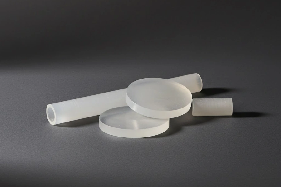
Fused Silica and Synthetic Quartz as Raw Materials in Parts Manufacturing
Among all variables that influence final component performance, raw material selection carries the greatest upstream consequence — a reality that experienced process engineers encounter repeatedly when tracing field failures back to material-level decisions.
The Structural Difference Between Fused Silica and Synthetic Quartz
Fused silica and synthetic quartz are chemically similar — both are predominantly silicon dioxide (SiO₂) — yet their production routes produce materials with fundamentally different internal structures and contamination profiles.
Fused silica is produced by melting naturally occurring quartz sand or quartz crystal at temperatures exceeding 1,700 °C, then rapidly cooling the melt to form an amorphous, non-crystalline glass. Because the feedstock is natural mineral, fused silica carries a background of metallic impurities — iron, aluminum, calcium, sodium — at concentrations typically in the range of 10 to 50 ppm depending on feedstock grade. Its hydroxyl (OH) content varies with production method: electric fusion yields low-OH material (below 5 ppm), while flame fusion produces high-OH variants (150–400 ppm OH), which exhibit superior UV transmission.
Synthetic quartz glass, by contrast, is manufactured through the vapor-phase oxidation or hydrolysis of silicon tetrachloride (SiCl₄) or silane (SiH₄) at elevated temperatures, a process that inherently excludes metallic contaminants from the feedstock chemistry. The result is a material with total metallic impurity levels below 1 ppm and exceptional optical homogeneity, making it the preferred substrate for deep-ultraviolet (DUV) optical elements and photolithography applications.
The practical consequence of this structural divergence is significant: synthetic quartz supports transmission wavelengths down to 160 nm, while standard fused silica is limited to approximately 200 nm, a distinction that directly governs material selection for UV-sensitive applications.
Key Property Comparison of Fused Silica and Synthetic Quartz
| Недвижимость | Fused Silica (Electric Fusion) | Fused Silica (Flame Fusion) | Synthetic Quartz Glass |
|---|---|---|---|
| SiO₂ Чистота (%) | 99.95 – 99.99 | 99.95 – 99.99 | > 99.9999 |
| Содержание OH (ppm) | < 5 | 150 – 400 | 0 – 1,200 (controllable) |
| Ультрафиолетовое пропускание (нм) | ~200 | ~170 | ~160 |
| Общее количество металлических примесей (ppm) | 10 – 50 | 10 – 50 | < 1 |
| Refractive Index Homogeneity (ppm) | 2 – 5 | 2 – 5 | < 0.5 |
| Типовое применение | Industrial furnace parts | UV lamps, optical windows | DUV optics, photolithography |
Purity Grading Standards and What Each Grade Covers
Purity classification in quartz raw materials follows a grading hierarchy built around SiO₂ content and residual metallic impurity thresholds, expressed in parts per million (ppm) or parts per billion (ppb) depending on grade sensitivity.
4N grade material (99.99% SiO₂) tolerates metallic impurities up to approximately 100 ppm collectively, making it suitable for general industrial applications such as chemical reaction vessels, infrared optical windows, and standard laboratory glassware where UV performance and ultra-low contamination are not primary requirements. 5N grade (99.999% SiO₂) reduces total metallic impurities to below 10 ppm and is the standard material for semiconductor diffusion furnace tubes, wafer carriers, and process chamber components where trace metal contamination would compromise device yield. At the highest tier, 6N grade (99.9999% SiO₂) brings metallic impurities into the sub-ppm range — below 1 ppm total — and is reserved for photolithography substrates, deep-UV transmission windows, and any application where material-sourced contamination must be effectively eliminated from the contamination budget.
Beyond bulk purity, hydroxyl content constitutes a separate grading axis. High-OH materials (OH > 100 ppm) exhibit superior UV transmission and lower fictive temperature, while low-OH materials (OH < 10 ppm) offer better thermal stability and reduced infrared absorption — a distinction that becomes critical when specifying material for laser optics versus high-temperature process components.
Quartz Raw Material Purity Grades and Application Mapping
| Класс | SiO₂ Чистота | Total Metallic Impurities | Типичное содержание OH (ppm) | Primary Application Domains |
|---|---|---|---|---|
| 4N | 99.99% | ≤ 100 ppm | Переменная | Industrial vessels, IR windows, lab glassware |
| 5N | 99.999% | ≤ 10 ppm | Low or high | Semiconductor furnace tubes, wafer carriers |
| 6N | 99.9999% | ≤ 1 стр. | Контролируемый | DUV optics, photolithography substrates |
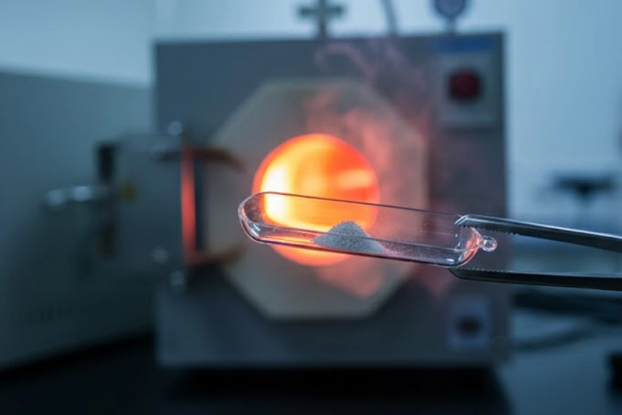
Raw Material Incoming Inspection and Purity Verification Methods
Purity certificates from material suppliers provide a starting point, but independent incoming inspection is standard practice in any manufacturing environment where component failure carries process or yield consequences.
Inductively coupled plasma mass spectrometry (ICP-MS) is the primary analytical method for quantifying metallic impurities at ppb-level sensitivity. A digested quartz sample is introduced into argon plasma at approximately 6,000–8,000 K, ionizing the constituent elements; the resulting ion beam passes through a mass spectrometer that resolves individual elements by mass-to-charge ratio with detection limits reaching 0.001 ppb for elements such as iron, aluminum, sodium, and calcium. This method provides a comprehensive elemental profile across 30 or more elements in a single analytical run.
Fourier-transform infrared spectroscopy (FTIR) quantifies hydroxyl content by measuring the characteristic OH absorption band at approximately 2.73 μm wavelength. The integrated absorbance of this band, combined with the sample thickness, yields OH concentration in ppm through Beer-Lambert law calculations — a non-destructive measurement that can be performed on production blanks without material consumption. Complementing chemical analysis, UV-Vis transmission spectroscopy characterizes the optical transmission window of each material lot from 160 nm to 2,500 nm, confirming that the material meets the specified cutoff wavelength for its intended application. Polarimetric stress inspection, conducted under crossed polarizers with a white light source, identifies residual internal stress, bubbles, and striae in bulk blanks before any machining begins — allowing rejection of defective stock before machining costs are incurred.

Glass Turning via CNC Lathe Operations in Quartz Parts Manufacturing
Rotational machining of quartz is the most broadly applied stock-removal process across component types, and the physics of cutting a brittle amorphous glass differs from metal turning in ways that make parameter selection critical to surface integrity.
How Diamond Tooling Removes Material from Quartz Without Fracture
The fracture behavior of amorphous quartz under cutting loads follows brittle fracture mechanics — a Hertzian contact stress field develops ahead of the tool edge, and if the stress intensity factor at crack tips exceeds the material's fracture toughness (K₁c ≈ 0.75 MPa·m^0.5), subsurface median and lateral cracks propagate and intersect the surface, producing chipping rather than a continuous chip.
Ductile-regime machining1 — the condition under which quartz behaves plastically at the tool-workpiece interface — is achievable only when the undeformed chip thickness is maintained below a critical depth of cut, typically in the range of 0.05 to 0.3 μm per cutting edge engagement for quartz glass. Diamond tooling enables this regime because the extreme hardness of diamond (Vickers hardness ≈ 10,000 HV) and its capacity to maintain a sharp cutting edge geometry — edge radii below 0.5 μm are achievable with polycrystalline diamond (PCD) inserts — concentrate the deformation zone to a scale where plastic flow dominates over fracture. Cemented carbide tooling, by contrast, cannot sustain the edge sharpness required to stay within the ductile-regime chip thickness window, resulting in brittle surface damage at industrially relevant material removal rates.
Tool geometry further governs the stress field distribution: negative rake angles between −25° and −45° are standard for quartz turning, as they place the cutting zone under compressive rather than tensile stress, suppressing crack opening at the machined surface.
Diamond Tool Geometry Parameters for Quartz CNC Turning
| Параметр | Recommended Range | Влияние на качество поверхности |
|---|---|---|
| Rake Angle (°) | −25 to −45 | Negative rake suppresses brittle fracture |
| Clearance Angle (°) | 6 – 12 | Reduces rubbing while maintaining edge support |
| Tool Nose Radius (mm) | 0.4 – 1.6 | Larger radius reduces surface roughness Ra |
| Edge Radius (μm) | < 0.5 (PCD) | Critical for ductile-regime chip formation |
Cutting Parameters and Coolant Selection for Quartz Lathe Work
Spindle speed, feed rate, and depth of cut interact non-linearly in quartz turning, and the operating window for crack-free surfaces is narrower than in metal machining — a fact that becomes apparent in the surface damage patterns that emerge when even one parameter drifts outside specification.
Spindle speeds for quartz turning typically range from 800 to 3,500 RPM, depending on workpiece diameter; larger diameters require proportionally lower RPM to maintain surface cutting speeds in the range of 30–80 m/min that support ductile-regime material removal. Feed rates are held between 0.01 and 0.05 mm/rev for finishing passes, with roughing passes permitted up to 0.15 mm/rev where surface integrity is secondary to material removal rate. Depth of cut in finishing operations is constrained to 0.02–0.10 mm per pass to remain within the subsurface stress field that ductile-regime cutting requires.
Coolant selection is not interchangeable. Deionized water or low-concentration water-soluble synthetic cutting fluids (concentration 3–5%) are standard for quartz machining, serving two functions simultaneously: thermal control at the cutting zone — where localized heat generation can induce thermal shock cracking in a material with a thermal expansion coefficient of only 0.55 × 10⁻⁶/°C — and chip evacuation, flushing SiO₂ particles away from the cutting zone before they become embedded in the machined surface or cause re-cutting abrasion. Oil-based cutting fluids are avoided because residual hydrocarbon contamination on quartz surfaces is difficult to remove cleanly and compromises subsequent bonding, coating, or optical measurement operations.
CNC Turning Parameters for Quartz Tube and Rod Stock
| Параметр | Roughing Range | Finishing Range | Единица |
|---|---|---|---|
| Скорость вращения шпинделя | 800 – 1,500 | 1,500 – 3,500 | RPM |
| Скорость подачи | 0.05 – 0.15 | 0.01 – 0.05 | mm/rev |
| Depth of Cut | 0.1 – 0.5 | 0.02 – 0.10 | мм |
| Скорость резки | 30 – 80 | 30 – 80 | m/min |
| Coolant Flow Rate | 8 – 15 | 5 – 10 | L/min |
Achievable Geometries and Dimensional Tolerances in Turned Quartz Components
CNC lathe operations on quartz are capable of producing a wider range of axisymmetric geometries than is commonly assumed, and tolerance capability has improved substantially as diamond tooling and machine rigidity have advanced over the past two decades.
Outer diameter (OD) and inner diameter (ID) turning on quartz tubes and rods routinely achieves dimensional tolerances of ±0.05 mm in production and ±0.02 mm under controlled finishing conditions with in-process measurement feedback. Taper and conical surfaces are machinable with half-angle accuracies within 0.1°, supporting applications such as tapered joints and ground glass cone-and-socket fittings used in laboratory apparatus. Thread cutting on quartz is achievable with coarse-pitch profiles (pitch ≥ 2 mm) using single-point diamond tools, though fine-pitch threading is generally avoided due to the risk of chipping at thread root radii below 0.3 mm. Step features, flanged ends, and recessed grooves are all within the capability envelope of modern CNC quartz turning centers equipped with sub-micron position feedback.
TOQUARTZ's CNC turning operations accommodate quartz tube and rod diameters from 4 mm to 350 mm OD, with length capacity up to 1,500 mm, supporting the full dimensional range required by semiconductor process equipment, laboratory instrument, and industrial component applications.
Dimensional Tolerance Capability for Turned Quartz Parts
| Характеристика | Стандартный допуск | Precision Tolerance | Единица |
|---|---|---|---|
| Внешний диаметр | ± 0.05 | ± 0.02 | мм |
| Внутренний диаметр | ± 0.05 | ± 0.02 | мм |
| Length / End Face | ± 0.1 | ± 0.05 | мм |
| Taper Half-Angle | ± 0.1 | ± 0.05 | ° |
| Surface Roughness Ra | 0.4 – 1.6 | 0.1 – 0.4 | μm |

Grinding and Polishing Sequences Applied to Precision Quartz Parts
Surface finish requirements on quartz components frequently exceed what CNC turning alone can deliver, particularly for optical elements, vacuum sealing faces, and metrology-grade flat surfaces — contexts where the transition from turned surface to polished surface represents a measurable performance threshold.
Abrasive Progression from Coarse Grinding to Fine Lapping
The material removal sequence in quartz surface finishing follows a structured abrasive progression, where each stage removes the subsurface damage introduced by the previous coarser stage — a principle that, when violated by skipping intermediate grits, results in residual subsurface cracks that polishing cannot eliminate.
Coarse grinding, typically with bonded diamond wheels or loose abrasive slurries at grit sizes between #80 and #220 (average particle diameter 60–180 μm), removes bulk material to bring the workpiece within 0.1–0.3 mm of final dimension while establishing gross surface geometry. The subsurface damage depth at this stage extends 15–40 μm below the machined surface. Intermediate lapping with #400 to #800 grit aluminum oxide or silicon carbide slurry (particle diameter 15–35 μm) reduces the surface roughness Ra from the 1–3 μm range typical of coarse grinding to 0.2–0.5 μm, simultaneously reducing subsurface crack depth to 3–8 μm. Each grit stage requires sufficient dwell time — typically 2 to 4 times the time needed to remove the visual scratch pattern from the previous stage — to ensure complete elimination of deeper damage before advancing.
Fine lapping with #1200 to #2000 grit cerium oxide or aluminum oxide slurry (particle diameter 3–9 μm) brings Ra to the 0.05–0.15 μm range and reduces subsurface damage to below 1 μm, establishing the surface condition from which polishing can achieve optical quality.
Abrasive Grit Progression and Surface Outcomes for Quartz Lapping
| Сцена | Abrasive Type | Зернистость | Particle Diameter (μm) | Ra Achieved (μm) | Subsurface Damage Depth (μm) |
|---|---|---|---|---|---|
| Coarse Grinding | Diamond wheel / SiC slurry | #80 – #220 | 60 – 180 | 1.0 – 3.0 | 15 – 40 |
| Intermediate Lapping | Al₂O₃ / SiC slurry | #400 – #800 | 15 – 35 | 0.2 – 0.5 | 3 – 8 |
| Fine Lapping | CeO₂ / Al₂O₃ slurry | #1200 – #2000 | 3 – 9 | 0.05 – 0.15 | < 1 |
| Полировка | CeO₂ polishing suspension | Sub-micron | 0.5 – 2 | < 0.01 | < 0.1 |
Mechanical Polishing and CMP Techniques for Optical Surface Quality
Optical polishing of quartz is a material removal process operating at the nanometer scale, where the removal mechanism transitions from purely mechanical abrasion to a combination of mechanical and chemical action — a transition that defines the difference between a lapped surface and a true optical surface.
Conventional mechanical polishing uses cerium oxide (CeO₂) polishing suspension — particle size 0.5–2 μm — applied to a polyurethane or pitch polishing pad on a rotating platen. The cerium oxide particles abrade the quartz surface while simultaneously participating in a mild chemical reaction with SiO₂ in the presence of water, forming a hydrated silica gel layer that is then removed by subsequent mechanical action. This combined mechanism enables surface roughness values of Ra < 0.5 nm and peak-to-valley (P-V) flatness of λ/10 (approximately 63 nm at 632.8 nm HeNe wavelength) on flat optical windows under controlled process conditions. Chemical mechanical planarization (CMP), adapted from semiconductor wafer processing, adds a chemically active slurry — typically an alkaline colloidal silica suspension at pH 10–11 — to a controlled-pressure, controlled-velocity polishing head, enabling superior planarity across large flat surfaces (300 mm diameter and above) with within-wafer non-uniformity (WIWNU) below 5%.
Surface quality specifications for optical quartz components are communicated using the MIL-PRF-13830B Scratch-Dig standard: a 10-5 designation indicates that the maximum allowable scratch width is 10 μm and the maximum allowable dig diameter is 0.5 mm — the standard required for high-performance laser optics and imaging windows. TOQUARTZ's polishing operations achieve Scratch-Dig ratings from 80-50 for general optical applications down to 20-10 for precision laser components.
Optical Polishing Surface Quality Standards for Quartz Components
| Quality Specification | Ra (nm) | P-V Flatness | Scratch-Dig (MIL-PRF-13830B) | Типовое применение |
|---|---|---|---|---|
| Commercial Optical | < 5 | λ/4 | 80-50 | General optical windows |
| Precision Optical | < 1 | λ/10 | 40-20 | Spectroscopy, sensors |
| Laser Grade | < 0.5 | λ/20 | 20-10 | Laser optics, lithography |
| Semiconductor Grade (CMP) | < 0.3 | < 100 nm TTV | Н/Д | Wafer-level components |

Laser Cutting Techniques for Quartz Parts with Complex Profiles
Where rotational geometry ends, laser processing begins — and for quartz components requiring non-circular contours, internal cutouts, or wafer-thin cross-sections, CO₂ laser cutting represents the only practical path to dimensional accuracy without mechanical edge damage.
CO₂ Laser Interaction with Quartz and the Thermal Removal Mechanism
The interaction between a CO₂ laser beam (wavelength 10.6 μm) and fused silica is governed by strong optical absorption: quartz absorbs over 98% of incident 10.6 μm radiation within a surface layer of approximately 10–15 μm, converting photon energy to heat at a spatial confinement that no mechanical tool geometry can match.
Within the absorption zone, energy deposition rates during pulsed operation reach 10⁶ to 10⁸ W/cm², sufficient to raise the local temperature from ambient to the SiO₂ vaporization point (approximately 2,230 °C) within microseconds. Material is removed primarily through sublimation and melt ejection, with a molten resolidified layer (recast layer2) typically 2–15 μm thick remaining on the cut edge depending on process parameters. This thermal removal mechanism eliminates the mechanical contact forces that cause edge chipping in saw or waterjet cutting of quartz, where Hertzian contact stresses at the cutting front initiate brittle fracture in the same way as overtly aggressive lathe cutting. Mechanical dicing of 1 mm thick quartz wafers typically produces edge chipping depths of 20–80 μm, while optimized CO₂ laser cutting of the same geometry yields edge chip depths below 5 μm.
The heat-affected zone (HAZ) surrounding the cut kerf extends 50–300 μm into the bulk material depending on pulse energy and scan speed, introducing residual thermal stress that may require post-cut annealing for stress-sensitive optical or semiconductor applications.
Comparison of Quartz Cutting Methods by Edge Quality
| Метод резки | Edge Chip Depth (μm) | HAZ Width (μm) | Geometric Accuracy (mm) | Suitable Thickness Range (mm) |
|---|---|---|---|---|
| Diamond Saw Dicing | 20 – 80 | None (mechanical) | ± 0.05 | 0.3 – 50 |
| Waterjet Cutting | 50 – 200 | Нет | ± 0.2 | 1 – 100 |
| CO₂ Laser Cutting | 2 – 10 | 50 – 300 | ± 0.05 | 0.1 – 10 |
| Ultrasonic Machining | 5 – 30 | Нет | ± 0.1 | 0.5 – 30 |
Pulse Parameters and Scan Strategies That Affect Cut Quality
Laser cutting of quartz is not a single-parameter process — the interaction between pulse energy, repetition rate, scan speed, and focal position determines whether the outcome is a clean cut with minimal HAZ or a thermally damaged edge with microcracks propagating into the bulk.
Peak pulse power in pulsed CO₂ cutting of quartz typically ranges from 200 W to 2,000 W depending on material thickness; insufficient peak power results in incomplete material removal per pulse, requiring more scan passes and increasing cumulative heat input, while excessive power causes melt ejection beyond the kerf boundaries, widening the recast layer. Pulse repetition frequency (PRF) interacts with scan speed to control pulse overlap — the fraction of each pulse footprint that overlaps with the previous pulse. Pulse overlap values of 60–80% produce smooth, continuous cut edges by ensuring that each point on the cut path receives multiple overlapping energy contributions that average out spatial intensity variations. Scan speeds for quartz cutting typically range from 5 to 50 mm/s, with thinner materials supporting higher speeds and reduced heat accumulation. Multi-pass cutting strategies — making 3 to 8 passes at reduced power rather than a single high-power pass — distribute thermal input across time, allowing partial heat dissipation between passes and reducing peak temperature in the HAZ.
Focal position relative to the material surface is set 0 to −30% of material thickness below the surface, placing the minimum beam waist (highest intensity) within the material rather than at the top surface, which reduces surface damage while maintaining energy density at the cut front.
CO₂ Laser Cutting Parameters for Quartz at Various Thicknesses
| Material Thickness (mm) | Peak Power (W) | PRF (Hz) | Scan Speed (mm/s) | Pulse Overlap (%) | Passes |
|---|---|---|---|---|---|
| 0.5 | 200 - 400 | 500 – 1,000 | 30 – 50 | 60 - 70 | 2 – 3 |
| 1.0 | 400 – 800 | 300 – 600 | 15 – 30 | 65 – 75 | 3 – 5 |
| 3.0 | 800 – 1,500 | 200 - 400 | 8 – 15 | 70 – 80 | 5 – 8 |
| 5.0 | 1,200 – 2,000 | 100 – 200 | 5 – 10 | 75 – 85 | 6 – 10 |
Applications of Laser-Cut Quartz in Semiconductor and Optical Industries
The application landscape for laser-cut quartz parts is anchored in industries where geometric precision, edge integrity, and material purity converge as simultaneous requirements — conditions that make CO₂ laser processing the preferred or only viable fabrication method.
In semiconductor front-end processing, quartz wafer carriers and boat inserts with precision slot profiles are laser-cut to slot pitch tolerances of ±0.05 mm and slot width tolerances of ±0.03 mm, ensuring consistent wafer spacing in diffusion and oxidation furnaces. Slot edge quality directly affects particulate generation: chipped quartz edges shed SiO₂ particles into the process environment, contaminating wafer surfaces and degrading device yield. Photolithography applications require quartz reticle substrates and pellicle frames cut to flatness tolerances below 5 μm TIR (total indicator reading) across 150 mm × 150 mm areas, with corner radii controlled to ±0.1 mm to maintain consistent membrane tension. In optical instrumentation, irregularly shaped quartz windows for spectroscopic sensors, environmental monitoring instruments, and high-power laser systems require contour accuracy within ±0.05 mm and edge chip depths below 5 μm to prevent stress concentration under thermal cycling.
TOQUARTZ's laser cutting capability covers quartz sheet and wafer thicknesses from 0.2 mm to 8 mm, with profile contour accuracy of ±0.05 mm, supporting prototype and production volumes across semiconductor, optical, and scientific instrument applications.

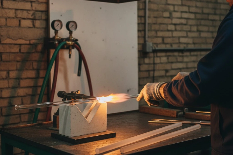
Flame Fusion Welding in the Fabrication of Complex Quartz Assemblies
Beyond individual machined components, many functional quartz assemblies require the permanent joining of multiple pieces into a single leak-free, thermally stable structure — a requirement that only flame fusion welding can satisfy without introducing incompatible adhesive or mechanical fastening materials.
Softening Behavior of Quartz Under Oxy-Hydrogen and Gas-Oxygen Flames
The workability of fused quartz in flame processing is controlled by its viscosity-temperature relationship, which spans seven orders of magnitude between room temperature and the working temperature used in torch operations.
Fused silica has a softening point of approximately 1,665 °C (defined as the temperature at which viscosity reaches 10^7.6 Pa·s), a working point of approximately 1,800–1,900 °C (viscosity 10^4 Pa·s), and an annealing point of approximately 1,140 °C (viscosity 10^13 Pa·s). These temperatures are significantly higher than those of borosilicate or soda-lime glass, requiring flame temperatures that only oxy-hydrogen or oxygen-natural gas combustion can reliably achieve. Oxy-hydrogen flames (H₂ + O₂) reach theoretical adiabatic flame temperatures of approximately 2,830 °C and are preferred for thin-wall tube work and precision joining operations, because the combustion products are water vapor only — eliminating carbon deposition risk on the quartz surface. Natural gas-oxygen flames (CH₄ + O₂) reach approximately 2,800 °C but produce CO₂ and water vapor as combustion products; while carbon deposition is not typically an issue with properly adjusted stoichiometry, the slightly lower energy density makes these flames better suited to larger-diameter tube assemblies where heat distribution over a wider area is more important than pinpoint thermal control.
The extremely low thermal expansion coefficient of fused silica (0.55 × 10⁻⁶/°C, approximately 10 times lower than borosilicate glass) means that thermal gradients induced by localized flame heating generate large internal stress differentials — a property that makes preheating of workpieces and controlled cooling after welding non-optional process steps.
Flame Type Comparison for Quartz Torch Welding Operations
| Flame Type | Максимальная температура (°C) | Combustion Products | Лучшее приложение | Carbon Risk |
|---|---|---|---|---|
| Окси-водород | ~2,830 | Только H₂O | Thin-wall tubes, precision joints | Нет |
| Natural Gas-Oxygen | ~2,800 | CO₂ + H₂O | Large-diameter assemblies | Low (adjusted stoichiometry) |
| Propane-Oxygen | ~2,526 | CO₂ + H₂O | Preheating, annealing | Низкий |
Joint Configurations and Torch Techniques for Quartz Tube Assemblies
The range of joint geometries achievable through flame fusion welding of quartz is broader than is commonly documented, and each configuration requires a distinct torch manipulation sequence to achieve a void-free, concentrically aligned joint.
Butt joints between same-diameter tubes are the most common configuration, executed by simultaneously heating both tube ends to working viscosity while maintaining axial alignment in a V-groove ceramic fixture, then advancing the two ends together under controlled pressure sufficient to close the joint gap without collapsing the tube bore. The completed joint zone shows a characteristic smooth external bead 2–4 mm wide and a corresponding slight internal bead that may require reaming if bore consistency is critical. T-joints and side-entry connections — where a smaller tube is fused into the wall of a larger tube — require localized flame application to an aperture pre-drilled or laser-cut in the main tube wall, followed by flame-shaping of the entry tube end to form a collar that fuses with the aperture perimeter. Achieving a leak-free T-joint requires matching the local wall temperature of both pieces simultaneously, a task that demands operator experience accumulated over hundreds of repetitions. Sealed end closures and tip-off seals used in lamp manufacturing, sensor housings, and vacuum enclosures involve collapsing a tube end under flame while simultaneously applying slight internal positive pressure or vacuum to control the final sealed geometry.
Concentricity in butt-welded assemblies is maintained by rotating both workpieces synchronously during the fusion phase — rotation speeds of 20–60 RPM are typical — ensuring that the softened glass zone distributes uniformly around the circumference rather than sagging to one side under gravity.
Joint Type Capabilities and Geometric Outcomes in Quartz Flame Welding
| Тип соединения | Типовое применение | Допуск на выравнивание | Bore Consistency | Leak Rate Achievable |
|---|---|---|---|---|
| Butt Joint | Tube extension, reaction vessel | ± 0.3 mm axial | ± 0.5 mm ID variation | < 10⁻⁹ mbar·L/s |
| T-Joint | Gas inlet ports, sampling connections | ± 0.5 mm | Н/Д | < 10⁻⁸ mbar·L/s |
| Flange Seal | Vacuum flanges, process connections | ± 0.2 mm | Н/Д | < 10⁻⁹ mbar·L/s |
| End Closure | Lamp envelopes, sensor housings | ± 0.2 mm | Н/Д | < 10⁻¹⁰ mbar·L/s |
Post-Weld Annealing to Relieve Thermal Stress in Fused Quartz Joints
The welding operation that joins two quartz pieces inevitably introduces a thermal stress distribution in the joint zone — and given quartz's negligible thermal expansion coefficient, even modest temperature gradients during cooling generate stress fields capable of initiating delayed fracture hours or days after fabrication.
The physical origin of weld-induced stress lies in the temperature differential between the fusion zone (at working temperature, ~1,800 °C) and the adjacent bulk material (at ambient or preheat temperature, typically 200–400 °C after preheating). As the fusion zone cools through the annealing point (approximately 1,140 °C) and into the brittle temperature range (below ~800 °C), viscous relaxation ceases and any remaining thermal gradient becomes frozen into the glass as permanent elastic stress. Without annealing, residual stress levels in the joint zone can reach 5–15 MPa — sufficient to cause spontaneous fracture in components subjected to subsequent thermal cycling, pressure loading, or even mechanical handling. Post-weld annealing begins by transferring the completed assembly into an annealing oven preheated to 1,050–1,100 °C within 60 seconds of completing the weld, preventing the joint from passing through the brittle temperature range before stress relief can occur. Soaking at 1,050 °C for 20–60 minutes (duration scaled to wall thickness — approximately 10 minutes per millimeter of wall thickness) allows viscous relaxation to reduce residual stress to below 0.5 MPa. Controlled cooling then proceeds at 2–5 °C/min through the annealing range (1,140 °C to 800 °C) and 10–20 °C/min below 800 °C, with the total cooling cycle from annealing temperature to room temperature requiring 4 to 12 hours for typical component sizes.
Annealing effectiveness is verified by polarimetric inspection under crossed polarizers with a sodium light source or monochromatic LED: residual stress двулучепреломление3 appears as color fringing or intensity variation at the joint zone, and components meeting specification show no visible birefringence under this examination at the sensitivity level corresponding to approximately 5 nm/cm optical path retardation. TOQUARTZ performs post-weld polarimetric inspection on 100% of flame-welded assemblies before dimensional finishing and packaging.
Post-Weld Annealing Parameters for Fused Quartz Assemblies
| Параметр | Технические характеристики | Примечания |
|---|---|---|
| Annealing Temperature (°C) | 1,050 – 1,100 | Above annealing point of 1,140 °C approach |
| Soak Duration (min/mm wall) | 10 | Scaled to maximum wall thickness |
| Cooling Rate: 1,140–800 °C (°C/min) | 2 – 5 | Critical stress-relief range |
| Cooling Rate: below 800 °C (°C/min) | 10 – 20 | Brittle range, faster cooling permitted |
| Residual Stress Target (MPa) | < 0.5 | Verified by polarimetric birefringence inspection |
| Birefringence Acceptance Limit (nm/cm) | < 5 | Under crossed polarizer inspection |
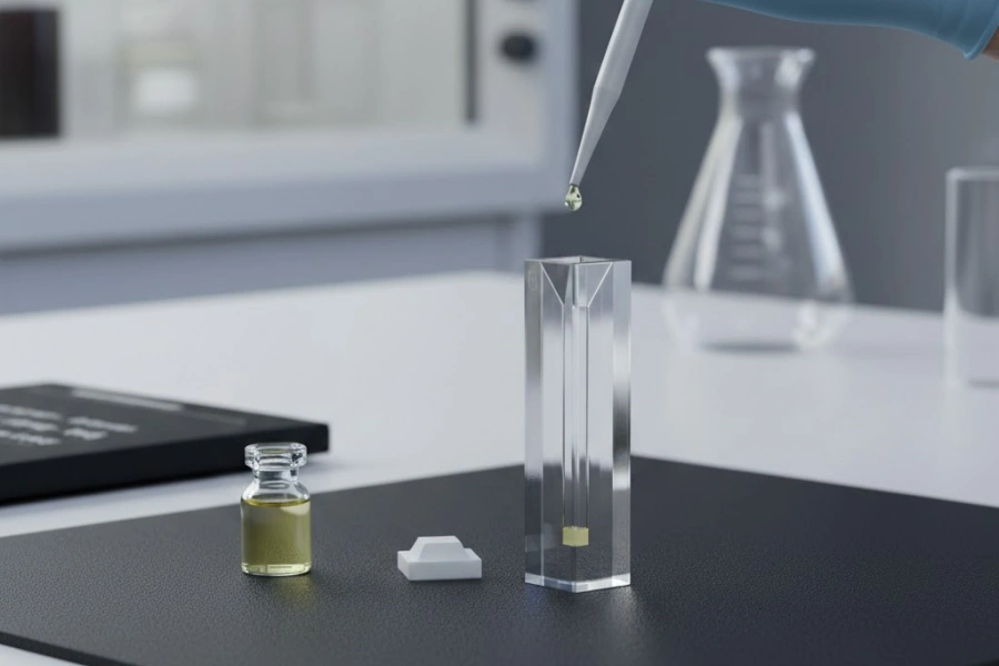
Dimensional and Optical Inspection Throughout Quartz Parts Manufacturing
Inspection in quartz component production is not a single end-of-line event but a sequence of verification stages integrated into the manufacturing workflow, with each stage providing feedback that either confirms process stability or triggers parameter adjustment before non-conforming material advances further.
- Coordinate Measuring Machine (CMM) inspection provides three-dimensional dimensional verification on complex geometries. Touch-trigger probes with ruby ball diameters of 1–3 mm measure critical dimensions — bore diameters, flange face perpendicularity, step heights — to uncertainties of ±0.003 mm under ISO 10360-2 calibration conditions. For cylindrical features, CMM roundness measurement characterizes out-of-roundness (OOA) and cylindricity, both of which affect sealing performance and assembly fit. Air gauging — pneumatic dimensional gauging — measures bore diameters at production rates, with repeatability of ±0.001 mm, suitable for inline measurement during CNC turning operations.
Surface texture and flatness measurement employs non-contact white-light interferometry (WLI) for optical-grade surfaces, providing Ra, Rq, and P-V flatness maps over measurement areas from 0.1 mm × 0.1 mm to 10 mm × 10 mm with vertical resolution below 0.1 nm. Contact stylus profilometry serves as the calibration reference for WLI measurements and provides surface texture data on non-optical surfaces where interferometry is impractical due to surface scatter.
-
Optical transmission measurement using UV-Vis-NIR spectrophotometry characterizes the spectral transmission of optical quartz components from 160 nm to 2,500 nm, with measurement uncertainty below ±0.3% transmittance. Fizeau interferometry measures transmitted wavefront error (TWE) on optical windows and lenses, quantifying the optical path difference introduced by thickness variation and refractive index inhomogeneity — a critical parameter for applications where wavefront quality affects system imaging performance. Acceptance criteria for precision optical windows typically require TWE below λ/10 (PV) at 632.8 nm.
-
Internal defect inspection relies on polarimetric birefringence measurement to detect residual stress from inadequate annealing, using a polarimeter calibrated to detect retardation levels as low as 2 nm/cm. Ultrasonic C-scan inspection identifies subsurface cracks, voids, and inclusions in thick-section components by mapping the reflection amplitude of a focused ultrasonic beam (typically 10–50 MHz) scanned across the component surface in a water-coupled configuration. Cleanliness verification — particularly important for semiconductor-grade components — involves liquid particle counting of a final rinse fluid to quantify surface particle contamination, alongside total organic carbon (TOC) measurement of the rinse water to confirm absence of hydrocarbon surface residue.
TOQUARTZ Custom Fabrication from Technical Drawing to Delivery
Translating a dimensional specification into a finished quartz component involves a sequence of coordinated steps that balance technical feasibility assessment, process planning, and quality verification before any component reaches the customer.
- Drawing submission accepts DWG, PDF, and STEP file formats. Submission triggers a technical review covering material specification, geometric tolerances, surface finish requirements, and any application-specific conditions such as cleanroom handling, UV transmission requirements, or high-vacuum compatibility. Technical review is completed within 3 to 5 business days, during which TOQUARTZ engineers assess manufacturability against current process capability and issue a detailed quotation with per-feature tolerance notes.
Prototype and sample fabrication follows approved drawing release. For components within standard process capability — turned tubes, flat lapped discs, laser-cut profiles — prototype lead times range from 7 to 15 business days. Assemblies involving flame fusion welding with post-weld annealing, or components requiring optical-grade polishing with interferometric verification, extend to 15 to 20 business days to accommodate the multi-stage process sequence and inspection hold points.
- Production batch lead times scale with order quantity and component complexity. Standard turned or laser-cut components in quantities of 10 to 100 pieces are typically completed within 15 to 25 business days. Complex assemblies or optically finished components in equivalent quantities require 25 to 35 business days, accounting for annealing cycles, polishing sequences, and full inspection documentation.
Outgoing quality documentation accompanies every shipment and includes a Certificate of Analysis (COA) confirming material grade and purity lot traceability, a dimensional inspection report with measured values and acceptance status for all specified tolerances, and a material certificate cross-referencing the raw material supplier's ICP-MS or FTIR data to the finished component lot. Components destined for semiconductor or cleanroom environments are packaged in double-bagged polyethylene film within anti-static foam-lined rigid boxes, with desiccant packets included for humidity-sensitive optical surfaces.
Заключение
Quartz parts manufacturing spans a sequence of technically interdependent stages — from raw material purity verification through CNC turning, surface grinding and polishing, laser profile cutting, and flame fusion welding — each of which sets the boundary conditions for the next. No single process step operates independently: material purity constrains achievable optical performance, machining parameters determine surface damage depth that subsequent polishing must remove, and weld thermal history dictates the annealing protocol required for stress-free joints. Understanding this interdependence is the foundation for specifying quartz components correctly and evaluating whether a manufacturing partner's process capability matches the application's actual requirements. TOQUARTZ's fabrication workflow addresses each of these stages with documented parameters, in-process inspection, and traceable quality records — providing the technical accountability that precision quartz applications demand.
ЧАСТО ЗАДАВАЕМЫЕ ВОПРОСЫ
What is the difference between fused silica and quartz glass in manufacturing contexts?
In industrial and manufacturing usage, "fused silica" typically refers to amorphous SiO₂ produced by melting natural quartz feedstock, while "synthetic quartz glass" refers to SiO₂ produced by chemical vapor deposition from silicon-containing precursor gases. Synthetic quartz achieves higher purity (6N grade, above 99.9999% SiO₂) and superior optical homogeneity compared to fused silica, making it the material of choice for deep-UV optical applications. Both materials are used in quartz parts manufacturing, with selection driven by purity requirements and spectral transmission specifications.
What surface roughness can be achieved on polished quartz optical components?
Optical polishing of quartz using cerium oxide suspension on polyurethane polishing pads routinely achieves surface roughness values of Ra below 0.5 nm under controlled process conditions. Laser-grade optical components polished using CMP techniques reach Ra values below 0.3 nm with peak-to-valley flatness within λ/20 at 632.8 nm. Surface quality is further characterized using the MIL-PRF-13830B Scratch-Dig standard, with precision laser optics typically specified at 20-10 and general optical windows at 80-50.
Why is post-weld annealing necessary after flame fusion welding of quartz components?
Fused silica has a thermal expansion coefficient of only 0.55 × 10⁻⁶/°C — approximately ten times lower than borosilicate glass. During flame welding, the joint zone reaches working temperatures above 1,800 °C while adjacent material remains at lower temperatures, creating a steep thermal gradient. As the joint cools below the annealing point (approximately 1,140 °C), viscous relaxation ceases and the residual temperature differential becomes frozen into the glass as elastic stress, which can reach 5–15 MPa without annealing — sufficient to cause delayed cracking. Post-weld annealing at 1,050–1,100 °C for 10 minutes per millimeter of wall thickness reduces residual stress to below 0.5 MPa.
What file formats does TOQUARTZ accept for custom quartz component fabrication?
TOQUARTZ accepts technical drawings and component specifications in DWG, PDF, and STEP file formats for custom fabrication inquiries. Following submission, a technical feasibility review is completed within 3 to 5 business days, covering material grade selection, geometric tolerance achievability, and surface finish requirements relative to current process capability.
Ссылки:
-
Ductile-regime machining is the cutting condition under which brittle materials such as quartz undergo plastic deformation rather than fracture at the tool-workpiece interface. ↩
-
The recast layer is the thin zone of resolidified molten material that forms on laser-cut edges, and its thickness and crystallinity directly affect the mechanical integrity and optical quality of the cut surface. ↩
-
Birefringence is the optical property by which a material exhibits different refractive indices along different axes, and in quartz components it serves as a measurable indicator of residual internal stress remaining after welding and annealing. ↩