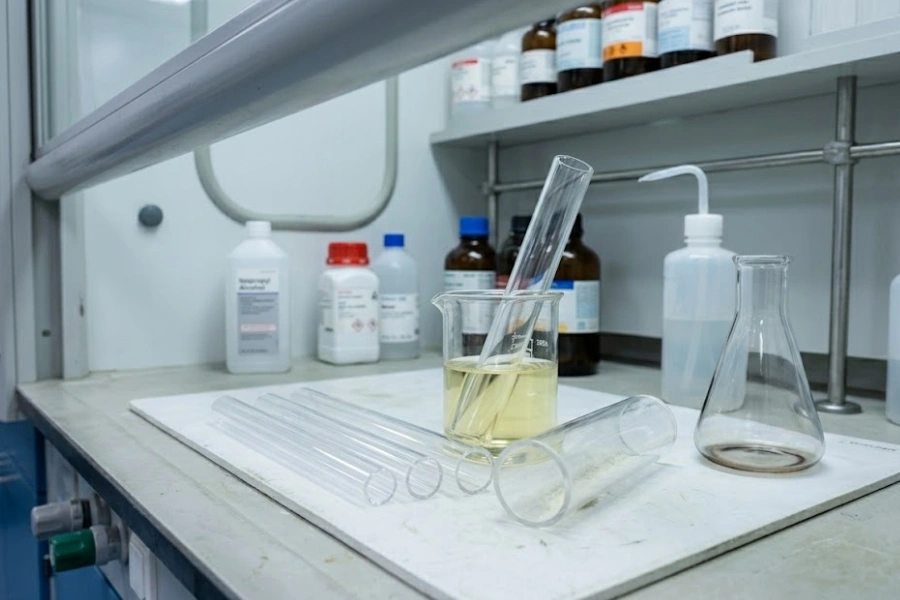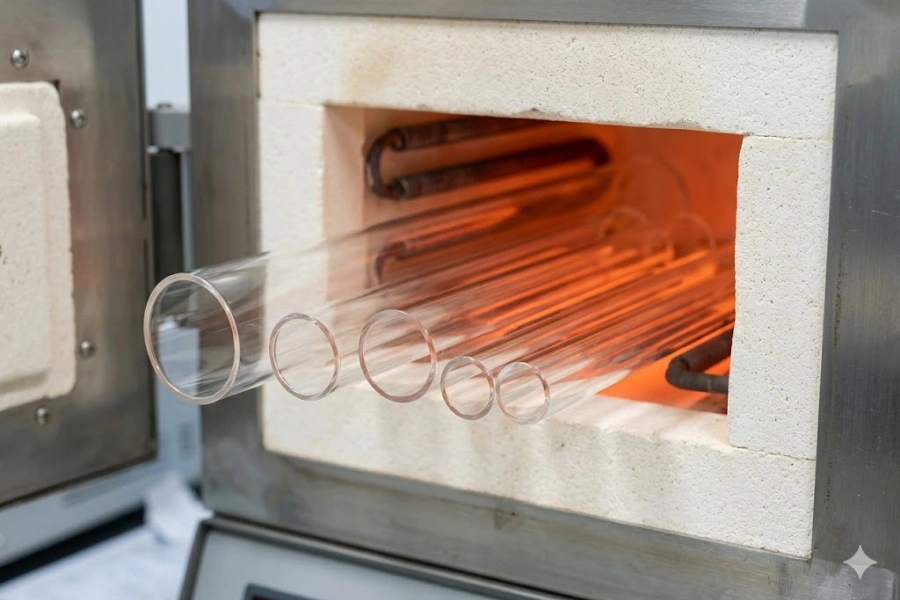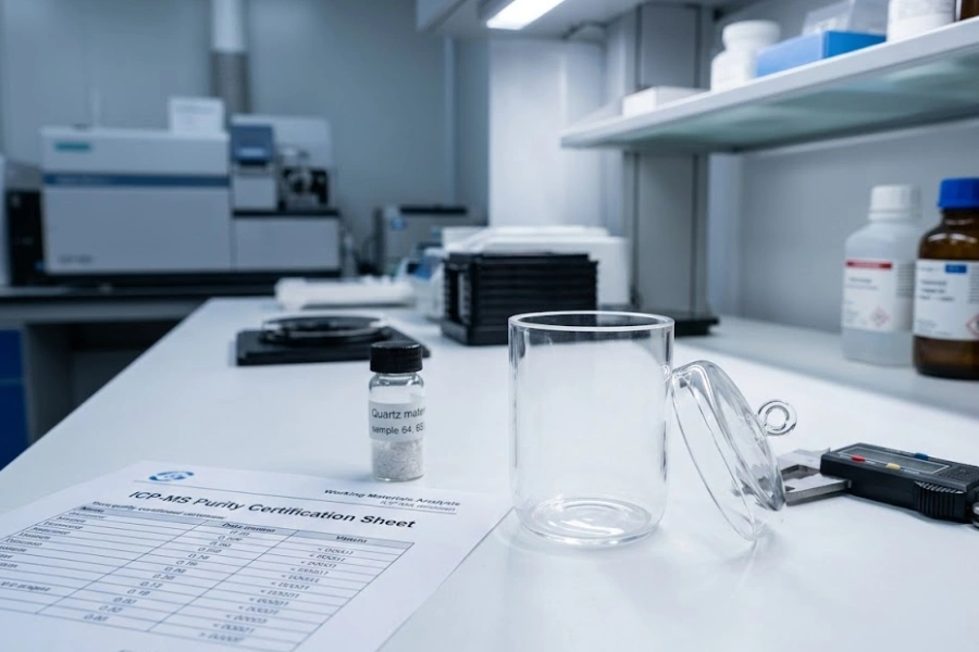
석영관은 아무런 전조 증상 없이 파손되며, 이로 인한 피해는 막대한 비용을 초래할 수 있습니다. 고온에서 발생하는 석영관 파손의 정확한 원리를 파악해야만 파손을 예방할 수 있습니다.
이 글에서는 용융 석영에서 발생하는 모든 주요 균열 메커니즘을 면밀히 분석한다. 순간적인 열충격부터 서서히 진행되는 비유리화, 분자 수준의 불순물 손상부터 조립에 의한 제약 응력에 이르기까지 다룬다. 각 설명은 재료과학에 근거하며 검증된 열 데이터로 뒷받침된다.
석영관 파손은 산업용 용광로 운영, 반도체 공정 및 화학 기상 증착(CVD) 환경에서 여전히 가장 큰 차질을 초래하면서도 가장 잘 이해되지 않는 재료 문제 중 하나입니다. 실제 현장에서 관찰되는 균열 양상은 단일 원인으로 발생하는 경우가 드물며, 열 물리학, 재료 화학, 기계적 하중 및 운영 이력이 복합적으로 작용하여 나타납니다. 특정 파손 메커니즘을 정확하게 규명하기 위해서는 분자 규모부터 시작해 융합 실리카가 어떻게 거동하는지에 대한 체계적인 이해가 선행되어야 합니다.
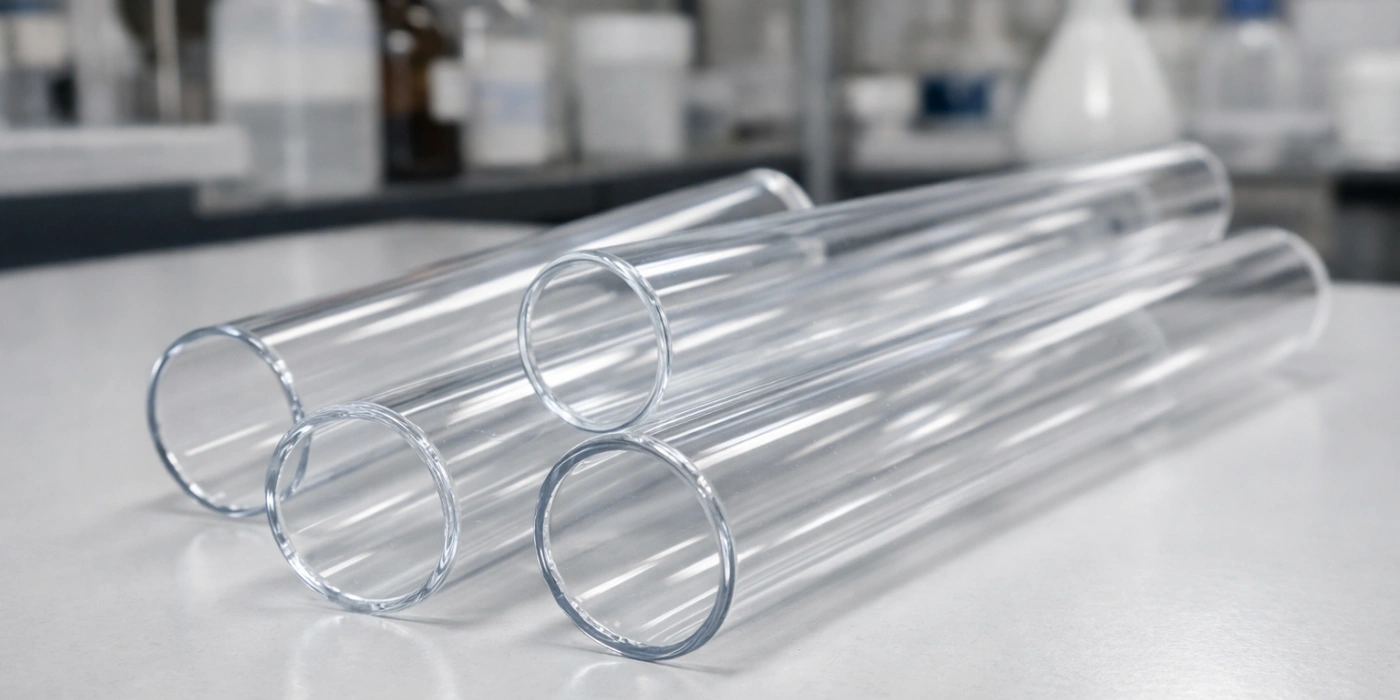
용융 석영 내의 비정질 실리카 네트워크
융합 석영은 일반 유리와는 다릅니다. 극한의 열 조건에서 나타나는 이 물질의 파단 거동은 그 고유한 분자 구조와 밀접한 관련이 있으므로, 균열 발생 메커니즘을 정확하게 해석하기 위해서는 이러한 기초 지식을 반드시 이해해야 합니다.
용융 실리카는 SiO₄ 사면체로 이루어진 연속적인 3차원 무작위 네트워크로 구성됩니다. 각 실리콘 원자는 네 개의 산소 원자와 공유 결합을 이루며, 각 산소 원자는 두 개의 실리콘 원자를 연결하여 무질서하지만 고도로 가교된 구조를 형성합니다. 주기적인 격자를 갖는 결정질 석영과 달리, 용융 석영은 장거리 질서가 없습니다. 이러한 비결정질 배열 덕분에 약 0.55 × 10-⁶/°C — 일반 보로실리케이트 유리에 비해 약 17배나 낮습니다.
이러한 낮은 열팽창계수(CTE) 덕분에 용융 석영은 일반 유리가 산산조각 날 정도의 급격한 온도 변화에도 견딜 수 있습니다. 그러나 이러한 장점을 제공하는 바로 그 비정질 네트워크가 동시에 취약점도 야기합니다. 결정 격자가 없다는 것은 제조 과정에서 발생했든 사용 중에 축적되었든 구조적 결함이 자가 치유되지 않는다는 것을 의미합니다. 불순물 원자, 하이드록실(OH) 기, 또는 미세 공극 등으로 인해 Si-O 네트워크에 국부적인 교란이 발생하면, 기계적 강도가 저하된 영역이 형성됩니다. 고온에서는 실리카 네트워크 내에서 점성 유동이 약 1,050°C, 그리고 재료는 강성 고체 상태에서 점탄성 상태로 전환됩니다. 이러한 전환은 균열 발생을 막지는 못하며, 단지 균열이 전파되는 메커니즘을 변화시킬 뿐입니다.
실온에서 용융 석영의 기계적 강도는 대략 48–55 MPa 인장 하중에서는 그렇지만, 이 값은 온도가 ~ 이상으로 올라가면 현저히 저하됩니다. 1,100°C 점성 이완이 시작되기 때문이다. 또한, 어떤 물체의 표면 상태는 석영 튜브 이는 매우 중요합니다. 화염 연마된 표면은 연마되거나 마모된 표면보다 응력을 훨씬 더 잘 견딜 수 있는데, 후자의 경우 튜브가 실제 사용에 들어가기도 전에 이미 깊이 10~50 μm의 미세 균열이 존재할 수 있습니다. 이러한 기존 결함은 응력 집중부 역할을 하여, 열 하중 조건에서 유효 파단 강도를 2배 이상 감소시킵니다.
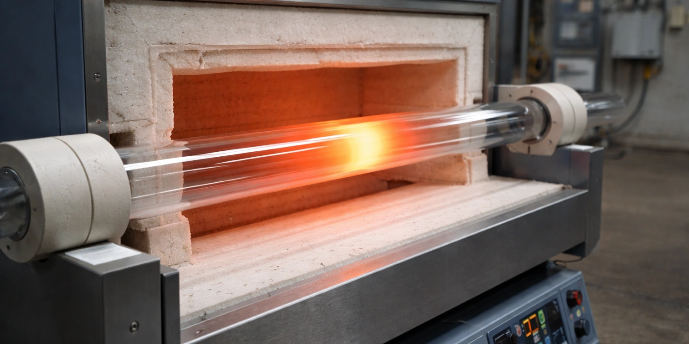
석영관의 열충격 — 주요 균열 발생 메커니즘
고온 실리카 부품에서 보고된 모든 고장 유형 중에서도, 열충격은 전 세계 사용 환경에서 관찰되는 갑작스럽고 치명적인 파손 사례 중 가장 큰 비중을 차지합니다.
열충격은 석영관의 벽면이나 전체 길이에 걸쳐 온도 구배가 너무 빠르게 형성되어, 이에 따른 열팽창 차이로 인해 재료의 파단 강도를 초과하는 응력이 발생할 때 발생합니다. 용융 실리카는 열전도율이 극히 낮기 때문에 — 약 1.4 W/m-K 실온에서 — 급격한 가열 또는 냉각이 일어날 때 열이 튜브 벽을 통해 균일하게 전달되지 않습니다. 외부 표면은 내부 내경보다 온도 변화에 더 빠르게 반응하여, 몇 초 만에 튜브가 파열될 수 있는 과도 응력 상태를 유발합니다. 이러한 메커니즘은 느리고 정상 상태의 열 부하와는 구별되며, 이는 전적으로 다음 요소에 의해 정의됩니다. 비율 온도 변화와 그에 따른 공간적 구배.
온도 구배가 어떻게 내부 응력을 발생시키는가
온도 구배에 의해 발생하는 응력은 열탄성 이론에서 잘 확립된 관계식에 의해 결정됩니다. 원통형 관의 경우, 벽 두께를 가로지르는 반경 방향 온도 구배 ΔT에 의해 유발되는 호방향 응력(σ_θ)은 다음과 같이 근사할 수 있습니다:
σ_θ = E × α × ΔT / (1 − ν)
여기서 E는 탄성 계수이며 (~72 GPa (용융 실리카의 경우), α는 열팽창 계수(CTE)이며 (~0.55 × 10-⁶/°C), 그리고 ν는 푸아송 비 (~0.17).
비록 미미한 반경 방향 온도 차이일지라도 200°C 두께 3 mm인 튜브 벽을 가로질러 발생하는 환형 응력은 다음 값에 근접할 수 있다. 8–10 MPa. 이는 용융 석영의 명목 인장 강도보다 훨씬 낮은 수치로 보이지만, 표면에 미세 균열이 존재함으로써 국부 응력이 2–5× 균열의 깊이와 형상에 따라 달라집니다. 따라서 열 구배 하중이 가해질 때의 유효 파단 임계값은 정적 인장 시험 데이터가 시사하는 것보다 훨씬 낮습니다.
가장 뜨거운 표면(내부이든 외부이든)은 압축 응력을 받고, 더 차가운 표면은 인장 응력을 받습니다. 융합 실리카는 다른 모든 취성 세라믹과 마찬가지로 인장 강도가 압축 강도보다 현저히 낮습니다. 이 물질의 압축 강도는 1,100 MPa, 반면 인장 강도는 거의 55 MPa 깨끗한 표면에서 시작하여 ~ 이하로 떨어지며 25 MPa 이미 손상이 있는 표면에서. 이러한 비대칭성 때문에 인장 균열은 거의 항상 가장 빠르게 냉각되는 표면에서 발생하게 된다.
파단은 일반적으로 최대 인장 응력 축에 수직인 표면 균열로 시작되어, 관 벽을 통해 방사형으로 안쪽으로 전파됩니다. 용광로에 급속히 적재한 사례 중 기록된 많은 경우에서, 균열 전선은 다음과 같은 속도에 근접한 속도로 이동합니다. 1,500 m/s — 인간의 시간 척도로 보면 사실상 순식간에 — 취성 규산염 파단에 전형적인 특징적인 조개껍질 모양의 파단면을 남기며.
석영의 허용 오차를 초과하는 임계 가열 및 냉각 속도
융합 석영은 열충격 저항성이 뛰어나다는 평판을 얻고 있지만, 가열·냉각 속도에 따른 파손을 완전히 피할 수는 없다. 튜브로 용광로 운영에서 얻은 경험적 데이터에 따르면, 특정 임계 가열 및 냉각 속도를 초과하면 파손 확률이 급격히 증가하는 것으로 일관되게 확인된다.
표준 두께의 석영관(벽 두께 2–4 mm)의 경우, 안전한 연속 가열 속도는 일반적으로 분당 5~10°C 미만으로 유지됩니다. 튜브를 용광로 내부에 삽입하고 제자리에 배치했을 때. 냉각 속도는 더욱 중요합니다. 강제 공기 냉각이나, 특정 온도 이상에서 주변 공기로의 급냉 등이 있습니다. 800°C 표면에 손상이 있는 튜브에 즉각적인 파단을 일으킬 만큼 충분한 열 구배를 발생시킵니다. 실제로는, 용광로 가동 정지 상태에서의 수동 냉각 일반적으로 분당 3~8°C의 냉각 속도를 나타내며, 대부분의 표준 튜브 구성에 있어 가장 안전한 조건으로 간주됩니다.
가장 위험한 열 현상은 기온이 가장 높은 것이 아니라, 온도 변화가 가장 급격한 경우입니다. CVD 및 확산로 운영에 관한 실험실 기록에 따르면, 튜브 파손의 대부분은 최고 온도에서의 정상 상태 작동 중이 아니라, 차가운 시료를 뜨거운로에 넣는 과정에서, 또는 갑작스러운 정전으로 인해 제어되지 않은 냉각이 발생하는 동안에 발생합니다. 1,150°C에서 수백 시간 동안 무사히 견뎌낸 석영관이라도, 제어된 예열 절차 없이 실온 상태의 시료 보트를 투입할 경우 10초도 채 되지 않아 파열될 수 있다.
융합 석영관의 안전한 온도 상승 속도
| 벽 두께(mm) | 최대 가열 속도 (°C/분) | 최대 냉각 속도 (°C/분) | 위험 온도 범위 (°C) |
|---|---|---|---|
| 1.5-2.0 | 15 | 10 | >600 |
| 2.0–3.0 | 10 | 5 | >700 |
| 3.0-4.0 | 8 | 4 | >750 |
| 4.0–5.0 | 5 | 3 | >800 |
| >5.0 | 3 | 2 | >850 |
열 균열의 숨겨진 원인으로서의 국부적 가열
모든 열충격이 용광로 전체의 온도 변동에서 비롯되는 것은 아닙니다. 튜브의 길이 또는 원주 중 일부 구간에만 영향을 미치는 국부적 가열은, 열충격만큼이나 파괴적이면서도 훨씬 덜 알려진 메커니즘입니다.
관형로 구조에서, 가열 구역과 가열되지 않은 관 연장부 사이의 과도 구역은 다음을 유지할 수 있다. 50°C/cm를 초과하는 축방향 온도 구배 불과 몇 센티미터에 걸친 구간에서 발생합니다. 이러한 구배로 인해 고온 영역 경계와 인접한 저온 영역에 축방향 인장 응력이 발생하는데, 이러한 응력 상태는 특히 튜브 둘레를 따라 전파되는 원주 방향 균열이 발생하기 쉬운 조건입니다. 이러한 균열은 종종 용광로 엔드 캡으로부터 일정한 거리에서 깨끗한 고리 모양의 파단으로 나타나는데, 이는 숙련된 용광로 운영자가 즉시 구배에 의한 고장으로 인식하는 특징적인 패턴입니다.
석영관과 저항 가열 소자, 유도 코일, 또는 고르지 않게 감긴 용광로 권선과 같은 국부적인 열원 간의 접촉은 원주 방향의 핫스팟을 발생시켜 응력 분포가 대칭 상태에서 벗어나게 합니다. 가열체에 더 가까운 튜브 원주 부위는 직경 반대편보다 80~120°C 더 뜨거울 수 있으며, 이로 인해 표준 축대칭 해석으로는 포착되지 않는 굽힘 모드의 열 응력이 발생합니다. 가열체가 부분적으로 감겨 있는 수평 튜브 용광로의 유한 요소 열 모델에서는 일반적으로 최대값이 나타납니다. 폰 미제스는 다음과 같이 강조한다1 이 비대칭 가열 영역에 집중된 튜브의 외표면에서.
석영관의 내경과 직접 접촉하는 세라믹 시료 보트나 지지대는 국부적인 응력 집중 부위를 추가로 발생시킵니다. 보트의 가장자리가 관 벽과 접촉하는 부분에서는 열전달이 전도 방식으로 이루어지며 열이 집중되는 반면, 주변 관 벽은 더 낮은 비율로 복사 가열을 받습니다. 이로 인해 발생하는 국부적인 온도 차는 30–80°C 폭이 불과 5~10 mm에 불과한 접촉 영역만으로도, 특징적인 별 모양으로 바깥쪽으로 퍼져 나가는 점발생 균열을 유발하기에 충분합니다.
열충격 균열 메커니즘 요약
| 메커니즘 | 스트레스 유형 | 골절의 원인 | 전형적인 균열 패턴 | 주요 위험 요인 |
|---|---|---|---|---|
| 전 세계적인 급격한 기온 상승 | 후프 (인장) | 외부 표면 | 축방향 균열 | 난방 속도 |
| 전 세계적인 급격한 냉각 | 후프 (인장) | 내경 | 축방향 균열 | 냉각 속도 |
| 핫존 경계 구배 | 축방향 (인장) | 냉대 지역 경계 | 원주 방향 링 균열 | 구배 길이 |
| 요소 접점의 국소화 | 굽힘 + 후프 | 연락처 | 별 모양 균열 또는 방사형 균열 | 비대칭 가열 |
| 냉각된 시료 주입 | 방사형 그라데이션 | 내경 표면 | 세로 분할 | 예시 예열 절차 |
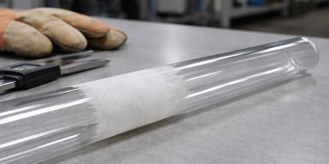
비유리화 및 구조적 무결성에 미치는 파괴적 영향
열충격이 갑작스러운 치명적 파손을 일으키는 반면, 비유화 현상은 서서히 누적되는 과정으로 작용하여, 2차 응력 현상이 발생해 최종 파단을 유발할 때까지 용융 석영의 구조적 무결성을 서서히 약화시킵니다.
탈비트리피케이션이란 비정질 용융 실리카가 일반적으로 ~ 이상의 온도에 장시간 노출되었을 때 결정질 상(대개 크리스토발라이트(SiO₂ 다형체))으로 자발적으로 결정화되는 현상을 말합니다. 1,050°C. 이 상변화는 고온에서 결정 상태가 비결정질 유리보다 자유 에너지가 낮기 때문에 열역학적으로 유리하다. 이로 인해 지속적으로 사용되는 모든 고온 석영관의 경우, 관벽 전체에 걸쳐 균일성, 광학적 투명도 및 기계적 신뢰성이 점차 저하되는 실질적인 결과가 발생한다.
비정질 실리카에서 크리스토발라이트로의 상변태
탈유리화 과정은 고전적 고체 상태 동역학에 의해 지배되는 고전적인 핵생성 및 성장 현상이다.
용융 실리카 내 크리스토발라이트의 핵형성이 일어나기 위해서는 활성화 에너지 장벽을 극복해야 합니다. ~ 사이의 온도에서 1,050°C 및 1,200°C, 핵생성 속도는 낮지만 0은 아니므로, 이러한 온도에서 장시간 노출하면 결국 감지 가능한 결정질 영역이 형성됩니다. 그 이상에서는 1,200°C, 결정 성장 속도가 급격히 빨라지며, 튜브 표면에 육안으로 확인할 수 있는 유백색의 결정성 반점이 나타날 수 있습니다. 10~50시간 순도와 표면 상태에 따라 지속적인 노출 기간이 달라집니다.
크리스토발라이트의 성장은 관벽 전체에 걸쳐 균일하게 일어나지 않는다. 이 과정은 주로 외부 표면에서 시작되는데, 이곳에서는 오염 물질, 표면 손상 및 대기 노출로 인해 실리카 네트워크의 흠집 없는 내부에서는 찾아볼 수 없는 핵형성 부위가 형성되기 때문이다. 사용 기간이 지난 석영 튜브에 대한 고해상도 X선 회절 연구 결과, 두께 50~500 μm의 결정질 표면층이 일관되게 관찰되며, 그 아래로 비정질 유리로 급격하게 전환되는 것이 확인되었습니다. 이러한 층상 구조는 결정질 외부 층과 비정질 내부 사이의 기계적 불일치가 사용 기간에 따라 점진적으로 증가하여, 외부 하중이 전혀 가해지지 않은 상태에서도 계면 응력을 유발함을 의미합니다.
변환 속도는 활성화 에너지가 대략 200–250 kJ/mol 고순도 용융 실리카의 경우. 이는 즉, 작동 온도 20°C 상승 비결정화 속도를 대략 두 배로 증가시키는데, 이러한 관계는 공칭 온도 한계 근처에서 운전되는 튜브에 중요한 시사점을 제공한다.
200–270°C에서의 역전 현상과 이에 따른 부피 변화
탈유리화의 가장 심각한 기계적 파괴적 결과는 결정화 그 자체가 아니라, 그 후의 냉각 과정에서 일어나는 현상이다.
크리스토발라이트는 두 가지 다형 형태로 존재합니다: β-크리스토발라이트 (약 270°C) 및 α-크리스토발라이트 (아래에 안정화됨 200°C). 탈유리화된 석영관이 이 상전이 범위 내에서 냉각될 때, 크리스토발라이트는 β상에서 α상으로의 변위 상전이를 겪으며, 이때 약 4.9%의 부피 수축. 이러한 변화는 매우 빠르게 일어나는데, 대략 200–270°C — 또한 이는 확산이 없는 재구성 변태이므로, 서서히 냉각한다고 해도 억제될 수 없다.
수축하는 결정질 표면층과 치수적으로 안정된 비결정질 핵 사이의 체적 불일치로 인해 결정질 층에 인장 응력이 발생하며, 이 응력은 대개 크리스토발라이트의 파단 강도를 초과한다., 이는 순수 용융 실리카의 값보다 상당히 낮은 수치입니다. 비정질 기판 위에 결정질 층이 형성된 이중층 모델을 기반으로 한 파단 역학 계산에 따르면, 표면 결정질 층의 인장 응력은 15–30 MPa β-α 전이 과정에서, 결정질 SiO₂ 상의 균열 임계값을 지속적으로 초과하는 값이 나타납니다. 그 결과, 비결정화 영역에 주로 미세한 표면 균열망이 형성되며, 이 균열망은 이후 어떤 열적 또는 기계적 하중이 가해지더라도 벽을 관통하는 파단의 개시점으로 작용합니다.
현장 관측 결과, 가동된 지 1,100°C 이상에서 200시간 이상 이전에는 아무런 위험도 없었던 일상적인 냉각 주기 중에도 빈번하게 자발적 파단이 발생하는데, 이는 축적된 크리스토발라이트 층에서 β-α 상전이로 인한 직접적인 결과이다.
비결정화 촉진제로서의 표면 오염
순수 용융 실리카의 탈유리화는 상당히 느리게 진행되기 때문에, 많은 산업용 응용 분야에서 긴 사용 수명을 감당할 수 있습니다. 그러나 표면 오염은 핵생성 장벽을 급격히 낮추고 전체 결정화 과정을 가속화합니다.
알칼리 금속 이온, 특히 나트륨(Na⁺)과 칼륨(K⁺)은 가장 강력한 탈유리화 촉진제입니다. 이러한 이온은 사람의 피부 접촉을 통해 발생할 수 있는데(지문에는 약 10–100 μg/cm²의 NaCl), 대기 중의 먼지 또는 공정 화학 물질에서 유래한 물질들이 SiO₂ 네트워크에 삽입되어 비정질 구조를 유지하는 가교 산소 결합을 파괴한다. 장갑을 끼지 않은 손으로 석영관 표면에 단 한 번만 접촉해도, 1,000°C 이상의 온도에서 50~100시간 이내에 국소적인 비유화 현상을 유발할 만큼 충분한 알칼리 오염이 발생할 수 있다.
수증기는 또 다른 유형이지만 그만큼 중요한 위험 요인을 초래합니다. 온도가 800°C, 대기 중 수분이나 공정 가스에서 유래한 OH 기가 튜브 표면의 변형된 Si-O-Si 결합과 반응하는데, 이 과정을 응력 부식 또는 정적 피로라고 합니다. 이 반응은 균열 선단의 유효 표면 에너지를 낮추어, 균열 전파에 필요한 응력 강도 계수를 20-40% 건조 조건에서의 균열 성장과 비교했을 때. 튜브 내부에서 가공되는 텅스텐, 몰리브덴 및 철 함유 재료에서 발생하는 금속 증기를 비롯한 금속 증기들이 내경에 침착되어, 조성상 구별되는 핵생성 부위를 형성하며, 이로 인해 외부 표면의 결정화와 동시에 내부 표면에서 비유리화가 시작된다.
비유리화 진행 과정 및 영향
| 사용 온도 (°C) | 발병 시간 (시간) | 영향을 받은 구역 | 반전 시 부피 변화 (%) | 표면 균열 위험 |
|---|---|---|---|---|
| 1,000–1,050 | >500 | 외부 표면만 | ~4.9 | 낮음 |
| 1,050–1,150 | 100–300 | 외부 50–200 μm | ~4.9 | 보통 |
| 1,150-1,200 | 50-100 | 외부 200–400 μm | ~4.9 | 높음 |
| >1,200 | 10-50 | 외부 및 내부 표면 | ~4.9 | 매우 높음 |
석영관과 인접 부품 간의 열팽창 불일치
융합 실리카의 본질적인 재료적 거동 외에도, 실제 설치 환경에서 발생하는 석영관 고장의 상당 부분은 관과 주변 하드웨어(플랜지, 엔드 캡, 지지 구조물 및 밀봉 부품 등) 사이의 기계적 접합부에서 기인합니다.
열팽창 계수가 서로 다른 이종 재료가 강체 또는 반강체로 접합된 후 온도 변화를 겪을 때 열팽창 불일치가 발생합니다. 고온용 석영관 어셈블리의 경우, 이는 거의 보편적인 현상입니다. 왜냐하면 용광로 제작에 사용되는 거의 모든 재료, 즉 스테인리스강, 인코넬2, 알루미나, 흑연 등은 용융 실리카보다 열팽창 계수가 현저히 높습니다.
석영에 있어 열팽창 계수가 의미하는 바
열팽창 계수는 온도가 1 단위 상승할 때마다 물질의 치수가 얼마나 변하는지를 수치화한 것으로, 10⁻⁶/°C(ppm/°C) 단위로 표시됩니다.
융합 실리카의 열팽창 계수(CTE)는 0.55 ppm/°C 이는 모든 공학 소재 중에서도 가장 낮은 수준에 속하며, 바로 이 때문에 치수 안정성이 요구되는 고온 용도에 선택됩니다. 그러나 가열 시 훨씬 더 크게 팽창하는 소재로 만들어진 부품과 튜브를 결합해야 할 경우, 이러한 낮은 열팽창 계수는 문제가 됩니다. 길이 500 mm의 용융 석영 튜브는 단지 0.28 mm 25°C에서 1,025°C로 가열될 때 — 즉, 1,000°C의 온도 상승이 일어날 때. 동일한 온도 상승 범위에서, 동일한 길이의 316 스테인리스강 피팅은 8.5mm, 미분값은 8.22 mm 즉, 접합면은 응력을 흡수하거나 재분배해야 한다.
이러한 차등 팽창으로 인해 발생하는 응력은 유연한 시스템에서는 탄력적으로 흡수되지 않고, 대신 조립체에서 가장 단단한 지점, 즉 예외 없이 석영관의 표면에 집중됩니다. 차등 팽창과 이에 의해 유발되는 응력 간의 관계는 구속 부재의 탄성 계수와 접합부의 형상에 따라 달라지지만, 직경 50 mm의 석영 튜브 외면에 비교적 약한 구속력이 가해지더라도 다음을 초과하는 환형 응력이 발생할 수 있다. 10 MPa — 표면 손상이 발생한 튜브의 유효 파단 임계치에 근접하고 있다.
CTE: 석영과 일반적인 조립 재료의 비교
| 재료 | CTE (ppm/°C) | CTE 비율 대 융합 석영 | 튜브 어셈블리에서의 일반적인 용도 |
|---|---|---|---|
| 융합 실리카 (석영) | 0.55 | 1.0× | 튜브 본체 |
| 알루미나 (Al₂O₃) | 8.1 | 14.7× | 마개, 지원선 |
| 316 스테인리스강 | 16.0 | 29.1× | 플랜지, 엔드 캡 |
| 인코넬 625 | 12.8 | 23.3× | 고온용 피팅 |
| 흑연 | 4.0–8.0 | 7.3–14.5× | 수용체, 지지봉 |
| 멀라이트 | 5.3 | 9.6× | 세라믹 엔드 씰 |
관 끝단 및 플랜지 접합부에서의 구속에 의한 응력
튜브-플랜지 접합부의 형상은 석영 표면에 가해지는 특정 응력 분포를 결정하며, 결과적으로 열에 의해 유발되는 균열의 위치와 방향을 좌우합니다.
O-링이나 개스킷으로 밀봉된 두 개의 견고한 플랜지 사이에 석영관을 고정해 놓은 상태에서, 이 조립체를 가열하면 플랜지 재질이 석영관보다 훨씬 더 빠른 속도로 반경 방향으로 팽창하게 됩니다. 실온에서 플랜지 내경이 석영관의 외경에 꼭 맞을 경우, 이러한 팽창 차이로 인해 플랜지 내공에 의한 튜브 외표면의 방사형 압축 — 겉보기에는 유익해 보이지만, 관 벽 내부에 상쇄적인 인장 환형 응력을 발생시키기 때문에 위험한 상태입니다. 두께가 3 mm인 관 벽의 경우, 5 MPa 방사형 외부 압축이 가해지면, 내경 표면에는 약 3–4 MPa, 이는 공정과 관련된 열 구배와 결합되어 내경 균열의 발생을 촉발할 수 있다.
일반적으로 임계 응력 집중은 튜브 단면에서 발생한다., 여기서 플랜지의 축방향 구속으로 인해 냉각 중에 튜브가 자유롭게 수축하지 못합니다. 작동 온도에서 냉각되는 동안 튜브 단면에 발생하는 축방향 인장 응력은 열수축률의 차이와 플랜지 조립체의 축방향 강성을 바탕으로 추정할 수 있습니다. 직경 50 mm의 석영 튜브를 구속하는 강철 플랜지의 경우, 냉각 시 900°C, 튜브 단면의 축방향 인장 응력은 최대 12–18 MPa — 응력 집중 계수 Kt가 2–3인 날카로운 튜브 모서리에서, 효과적으로 국부 응력을 발생시키는 값은 24–54 MPa 단면 균열을 유발할 수 있다.
이음부 형상 및 균열 위치
| 조인트 유형 | 확장 방향 | 응력 집중 위치 | 주요 응력 모드 | 균열 패턴 |
|---|---|---|---|---|
| 밀착형 강성 플랜지 | 방사형 | 튜브 내경 중간 벽면 | 인장 후프 (내부) | 축방향, 내경 |
| 축 방향으로 고정된 엔드 캡 | 축방향 | 튜브 단면 | 축방향 인장 | 원주 방향 끝단 균열 |
| 세라믹 플러그 마찰 결합 | 방사형 + 축방향 | 플러그 단면 근처의 튜브 ID | 복합 이축 | 플러그 깊이에서의 링 균열 |
| 가이드에 고정되지 않은 튜브 | 측면 굽힘 | 접촉 지점의 튜브 외경 | 굽힘 인장 | 세로 균열 |
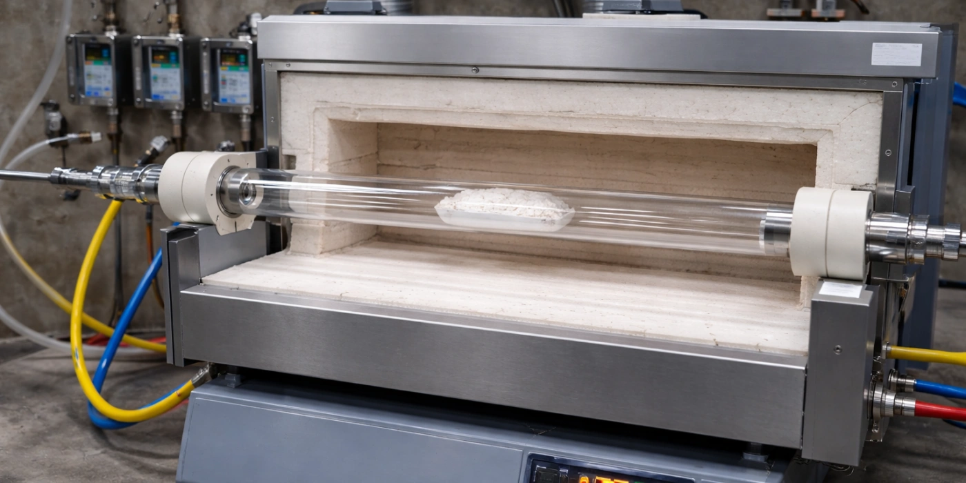
균열을 유발하는 기계적 응력 집중
온도 구배와 무관한 순수한 기계적 하중은 석영관의 파손을 초래하는 뚜렷하면서도 종종 과소평가되는 원인 중 하나로, 작동 온도가 상승하고 재료의 연성이 감소함에 따라 점차 더 위험해집니다.
온도가 상승하면 용융 실리카의 탄성 계수가 감소하고, 점성 변형이 전체 변형 반응에 기여하기 시작합니다. 이러한 점탄성 거동은 고온에서 가해지는 기계적 응력이 시간에 따라 변화하는 변형, 즉 크리프를 유발하여, 하중 집중을 탄성적으로 저장하기보다는 재분배한다는 것을 의미합니다. 역설적이게도, 이로 인해 고온에서의 기계적 하중은 실온에서의 하중보다 더 교묘한 위험을 초래합니다. 크리프 변형은 초기에는 응력을 완화하는 것처럼 보일 수 있지만, 누적된 변형은 영구적인 구조적 변화를 남기며, 이는 이후 냉각 과정에서 파괴 저항을 저하시킵니다.
파단 개시 부위로서의 표면 결함 및 미세 균열
융합 석영의 파괴 거동은 균열 전파에 필요한 임계 응력을 재료 내의 기존 결함 크기와 연관 짓는 그리피스 기준에 의해 상당한 정도까지 결정된다.
그리피스 파단 역학에 따르면, 깊이 a 는:
σ_f = K_IC / (Y √(πa))
여기서 K_IC는 파괴 인성이며 (~0.75 MPa·m⁰.⁵ (용융 실리카의 경우)이며, Y는 기하학적 계수입니다(표면 균열의 경우 ~1.12). 불과 25 μm 깊이가 증가함에 따라 국부 파단 응력은 대략 24 MPa — 깨끗한 표면의 명목상 강도의 절반에도 미치지 못한다. 마모성 접촉, 다이아몬드 절삭 공구, 또는 공정 가스 흐름에 포함된 알루미나 입자 등으로 인해 발생하는 흠집은 일상적인 취급 및 작동 과정에서 이 크기 범위의 표면 결함을 유발할 수 있습니다.
반도체 확산로 환경에서 고장 난 석영관의 주사전자현미경(SEM) 파단면 분석 결과, 파단 원인은 재료 내부 결함이 아닌 표면 특징(스크래치 자국, 모서리 파손, 공구 접촉 자국 등)인 것으로 일관되게 확인된다. 다음을 포함한 일련의 고장 분석에서 47건의 튜브 골절 여러 용광로 설비 전반에 걸쳐, 89%의 골절 ~에서 비롯되었다 3 mm 길이의 감지 가능한 표면 불연속부, 이는 표면 무결성 관리가 기계적 원인으로 발생하는 고장을 제어하는 데 있어 가장 직접적인 수단임을 확인해 준다.
열 환경은 이러한 취약성을 더욱 심화시킵니다. 온도가 800°C, 응력 부식(균열 끝단에서 수증기가 변형된 Si-O 결합과 반응하여 발생하는 아임계 균열 성장)으로 인해, 그리피스 임계값보다 훨씬 낮은 응력 조건에서도 균열이 점진적으로 성장할 수 있습니다. 때때로 ‘정적 피로’라고도 불리는 이 메커니즘은, 표면에 25 μm의 흠집이 있는 튜브가 초기 하중에는 견딜 수 있지만, 이후에는 파손될 수 있음을 의미합니다. 시간 또는 일 실온에서는 절대로 파단을 일으키지 않을 정도의 지속적인 응력을 받는 상태에서 장기간 사용했을 때.
열을 받는 긴 석영관의 굽힘 응력과 점하중 응력
수평형 용광로 구조에 사용되는 긴 석영관은 중력에 의한 굽힘 하중을 받는데, 이는 표준 설치 절차에서는 종종 간과되지만 고장 분석에서는 지속적으로 주요 원인으로 지목된다.
직경이 길이 1,200 mm, 외경 60 mm및 벽 두께 3.5 mm 자체 중량이 약 1.8 kg. 양단 지지된 단순 보 이론에 따르면, 자중만으로 인한 관의 중간 지점에서의 최대 굽힘 응력은 대략 2.5 MPa. 이 값은 단독으로 보면 미미하지만, 열 응력에 더해질 뿐만 아니라, 더 중요한 점은 튜브 내부에 적재된 시료 용기의 무게로 인해 발생하는 응력에도 더해진다는 것입니다. 500 g의 분말을 담은 세라믹 시편 용기를 1,200 mm의 스팬 중앙에 배치하면, 스팬 중앙부의 굽힘 응력이 3–4 MPa 더 증가한다., 이로 인해 합산된 기계적 응력이 기존 표면 손상과 위험하게 상호작용할 수 있는 수준에 이르게 됩니다.
온도가 1,000°C, 용융 실리카는 지속적인 하중이 가해질 때 크리프 변형이 누적되는 점성 유동 영역에 진입합니다. 일반적으로 다음과 같은 조건에서 연속적으로 작동하는 수평 관형 용광로의 경우 1,100°C, 측정 가능한 중간부 처짐 — 크리프로 인한 영구적인 하향 변형 — 이 발생할 수 있습니다. 500~1,000시간 작동 시. 이러한 점진적인 변형은 단순한 치수 변화 그 이상으로, 튜브 벽면의 응력 상태를 재분배하여 스팬 중앙부의 외부(하단) 표면에 인장 응력을 발생시키며, 이는 열 응력 및 표면 손상과 복합적으로 작용한다. 영구 처짐이 약 2~3mm를 초과하면, 이 튜브는 기계적 결함이 있는 것으로 간주되며, 이후 발생하는 모든 온도 변동 시 파손 위험이 높아집니다.
긴 수평 석영관의 기계적 응력 요인
| 매개변수 | 가치 | 응력 기여도 (MPa) | 골절 위험 배수 |
|---|---|---|---|
| 자중 굽힘 (스팬 1,200 mm) | 1.8kg 튜브 | ~2.5 | 기준치 대비 1.0배 |
| 시료가 실린 보트 (500g, 중앙) | 추가 하중 | +3.0–4.0 | 2.2–2.6× |
| 표면 미세 균열 (25 μm) | 응력 집중 | 유효 강도 ↓50% | ~2.0배 |
| 1,100°C(크리프 시작 온도)에서 작동 | 점탄성 영역 | 누적 처짐 | 진보적 |
| 1,000°C 이상에서의 복합 하중 | All factors active | >8–10 MPa effective | Critical zone |
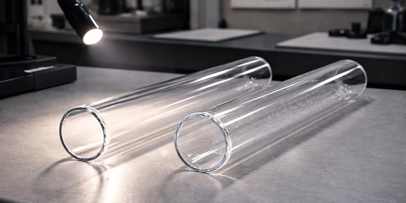
High-Purity Quartz versus Standard-Grade Tubes at Elevated Temperatures
Not all quartz tubes sold under the same product description perform identically at high temperature, and the differences in fracture resistance between purity grades are far larger than most users anticipate when selecting tubing for critical applications.
The purity of fused silica — defined by the total concentration of metallic and non-metallic impurities in parts per million (ppm) by weight — directly determines both the temperature at which the material begins to soften and devitrify, and the density of structural defects that act as crack initiation sites. Impurity content is not a secondary specification; it is a primary determinant of service life under thermal loading.
How Impurity Content Weakens the Silica Network
The Si-O tetrahedral network of fused silica achieves its exceptional thermal and mechanical properties only when fully cross-linked and free from network-modifying impurity atoms.
Network-modifying cations — including Na⁺, K⁺, Ca²⁺, Al³⁺, and Fe³⁺ — occupy interstitial positions within the SiO₂ network and disrupt bridging oxygen bonds. Each non-bridging oxygen created by a monovalent modifier like Na⁺ reduces the overall cross-link density of the network, lowering the viscosity of the glass at a given temperature and shifting the softening point downward. For every 100 ppm increase in total alkali content, the effective softening point of fused silica decreases by approximately 5–15°C, and the temperature at which viscous creep becomes mechanically significant drops proportionally.
Hydroxyl (OH) groups, which are incorporated into the silica network during the manufacturing process, behave similarly. Synthetic fused silica produced by flame hydrolysis or chemical vapor deposition contains 100–1,200 ppm OH by weight, while electric fusion grades of natural quartz contain typically <5 ppm OH. High OH content lowers the viscosity of the glass network at elevated temperatures, accelerating creep and reducing the effective working temperature ceiling by 50–100°C compared to low-OH grades. Furthermore, OH groups act as nucleation sites for cristobalite formation, meaning that high-OH tubes are intrinsically more susceptible to devitrification at a given operating temperature.
Dissolved gas inclusions — predominantly microscopic bubbles of SO₂, CO₂, or inert gas trapped during manufacture — represent mechanical defects rather than chemical ones. A bubble of 50 μm diameter within a quartz tube wall acts as an internal Griffith flaw with an effective stress concentration factor of approximately 2, reducing the fracture strength of the surrounding material in the same manner as a surface microcrack of equivalent size.
Synthetic versus Natural Quartz Tubes and Their Fracture Resistance
The fundamental distinction in commercial quartz tubing is between material produced from natural quartz mineral feedstock and that produced by synthetic chemical processes, and this distinction has direct consequences for fracture behavior under thermal loading.
Natural quartz-derived fused silica, produced by electric melting of high-purity quartz sand or lump crystal, typically contains 10–30 ppm total metallic impurities and 1–10 ppm OH. This material is designated as Type I or II fused silica in the ASTM classification and is suitable for operating temperatures up to approximately 1,100°C for continuous service. Above this temperature, the residual impurity content becomes sufficient to accelerate devitrification and creep to rates that compromise structural integrity within a few hundred hours. Standard natural quartz tubes exhibit a softening point of approximately 1,665°C and a working point (viscosity of 10⁴ Pa·s) at around 1,530°C, but these headline figures apply only to pristine material unaffected by contamination or crystallization.
Synthetic fused silica (Type III and IV), produced by vapor-phase hydrolysis of SiCl₄ or by plasma fusion of high-purity silica powder, achieves metallic impurity levels below 1 ppm and offers dramatically superior resistance to devitrification and high-temperature creep. Tubes manufactured from synthetic material — commercially designated as GE 214, Heraeus Suprasil, or equivalent grades — can sustain continuous service at 1,200°C with devitrification onset times three to five times longer than natural quartz equivalents under identical contamination conditions. The trade-off is that synthetic grades contain higher OH levels (typically 150–1,000 ppm), which lowers UV transmission and modifies viscosity characteristics but does not compromise mechanical performance in the thermal ranges relevant to most furnace applications.
Fused Silica Grade Comparison for High-Temperature Tube Applications
| 속성 | Type I (Natural) | Type II (Natural, OH-stripped) | Type III (Synthetic, high OH) | Type IV (Synthetic, low OH) |
|---|---|---|---|---|
| Total metallic impurities (ppm) | 20-50 | 10-30 | <1 | <1 |
| OH content (ppm) | <5 | <5 | 150–1,000 | <10 |
| Continuous use temp. (°C) | ~1,050 | ~1,100 | ~1,200 | ~1,200 |
| Devitrification onset (hrs at 1,100°C) | 50–150 | 100-250 | 300–700 | 300–700 |
| Bubble density (inclusions/cm³) | 더 높음 | 보통 | 낮음 | 매우 낮음 |
| Fracture toughness K_IC (MPa·m^0.5) | 0.72–0.75 | 0.73–0.76 | 0.74–0.77 | 0.74–0.77 |
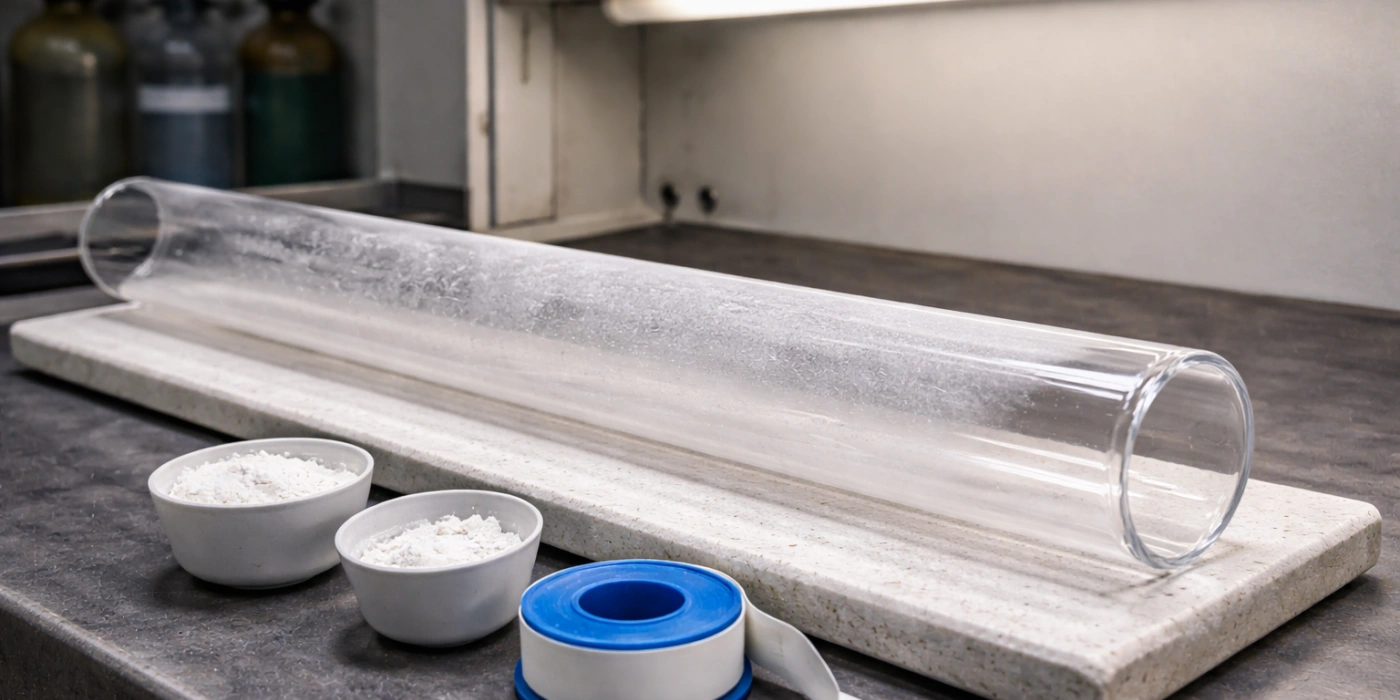
Moisture, Atmospheric Contaminants and Quartz Tube Degradation
Chemical attack from the operating environment contributes to quartz tube degradation through mechanisms that operate in parallel with thermal and mechanical stress, often rendering the tube surface more vulnerable to all other failure modes simultaneously.
-
Water vapor and hydroxyl corrosion: 온도가 800°C, water vapor in the furnace atmosphere reacts with strained Si-O-Si bonds at the tube surface through the reaction Si-O-Si + H₂O → 2(Si-OH). This reaction, known as hydrolytic weakening, reduces the energy required to propagate a crack through the silica network by 20-40% because the newly formed Si-OH bonds at the crack tip are weaker and more easily displaced than bridging Si-O-Si bonds. In moist atmospheres (relative humidity >50% at room temperature translates to significant partial pressures of water vapor at elevated tube entry zones), the sub-critical crack growth rate can increase by more than an order of magnitude compared to dry conditions, dramatically shortening the time from crack initiation to through-wall fracture. Tubes used in steam-containing atmospheres or in processes involving water-bearing precursors are particularly susceptible, and their service life should be assessed against moisture-corrected fracture mechanics data rather than dry-condition specifications.
-
Alkali and metal vapor deposition: Many high-temperature processes — including the sintering of ceramic powders, the annealing of metal components, and the pyrolysis of organic precursors — generate volatile species that deposit on the inner bore of the quartz tube. Alkali oxides from ceramic binders, iron oxide vapors from steel annealing, and tungsten or molybdenum oxides from metal processing all deposit as thin films on the tube's inner surface. At operating temperature, these deposits react with the SiO₂ surface to form silicate phases with compositions and thermal expansion coefficients distinct from pure fused silica. Upon cooling, the thermal expansion mismatch between these silicate surface films and the underlying silica generates tensile stresses in the tube wall that can reach 5–15 MPa — sufficient to initiate surface cracking in combination with any existing damage. This mechanism is particularly insidious because the deposits are often invisible at operating temperature and only become apparent as discolored patches upon tube removal.
-
Acid and reducing atmosphere effects: Halogen-containing process gases — including HF, HCl, and Cl₂ used in semiconductor cleaning and deposition processes — attack the SiO₂ surface through volatilization3 reactions that progressively thin the tube wall. At 1,000°C, the etch rate of fused silica in a 10% HCl atmosphere is approximately 0.5–2 μm/hour, meaning that a tube in continuous halogen-containing service loses measurable wall thickness over hundreds of operating hours. This wall thinning is not uniform; it preferentially attacks zones of higher surface energy — scratches, devitrified regions, and grain boundaries — creating locally thinned areas where the effective stress under thermal loading is amplified by the ratio of nominal to residual wall thickness. Reducing atmospheres containing hydrogen at elevated temperatures can promote silica reduction at the surface, generating SiO vapor and leaving a porous, weakened surface layer with substantially reduced fracture strength.
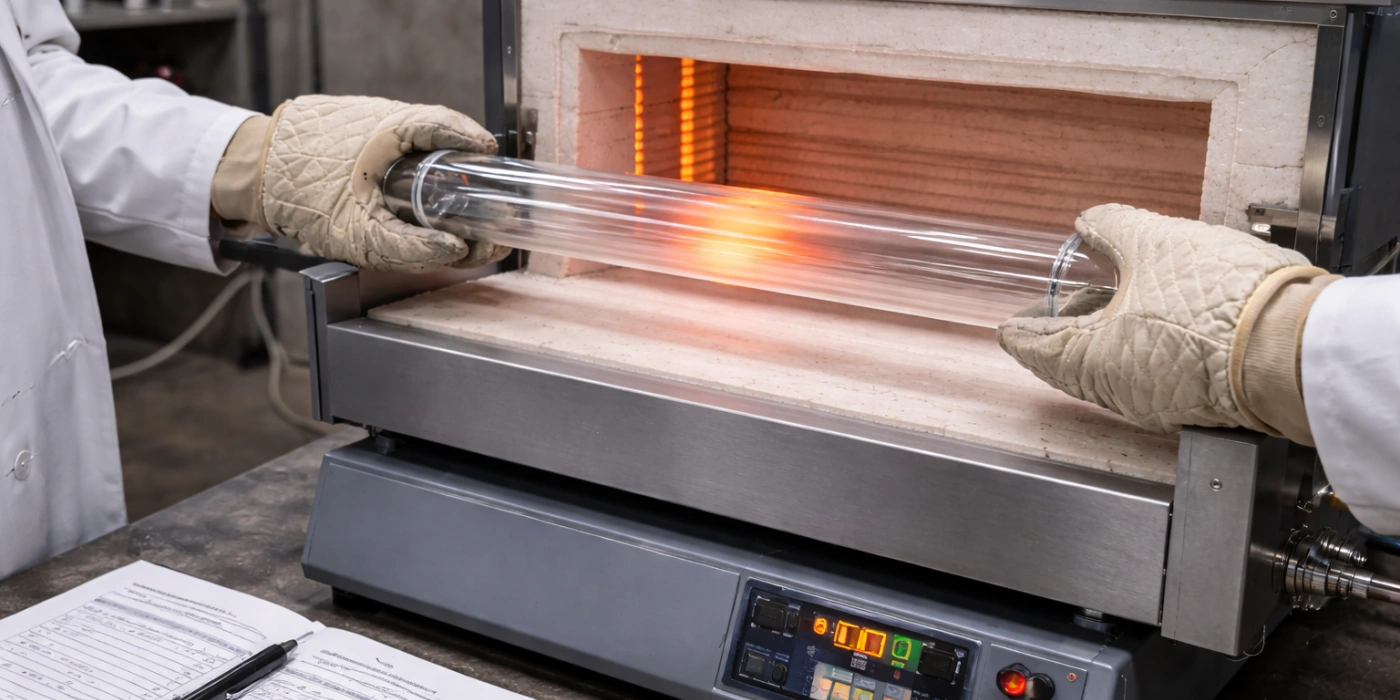
Why Quartz Tubes Fail Faster with Repeated Thermal Cycling
Cyclic thermal loading imposes a cumulative mechanical history on quartz tubes that no single-cycle analysis can capture, and understanding this history is essential for predicting when tubes that appear structurally sound will fail without apparent cause.
-
Fatigue crack accumulation mechanism: Unlike metals, which exhibit well-characterized fatigue behavior governed by dislocation motion, fused silica is a brittle material for which classical fatigue — in the sense of cyclically induced plasticity — does not apply. Nevertheless, thermal fatigue in quartz is real and well-documented, operating through the progressive extension of pre-existing surface microcracks during each thermal cycle. In each heating phase, tensile stresses on the cooler tube surfaces cause microcracks to open and extend incrementally. In each cooling phase, the same cracks close under compressive stress but do not heal — the crack tip has advanced slightly, and the effective flaw size has increased. After N thermal cycles, a surface crack that was initially 10 μm deep may have grown to 40–80 μm, reducing the local fracture stress by a factor of two or more and making the tube vulnerable to fracture under stresses that posed no threat on the first cycle. Data from tube furnace operations in academic and industrial settings indicate that the majority of quartz tube failures in multi-cycle operations occur between cycle 50 and cycle 200, corresponding to a crack growth regime where accumulated damage crosses the threshold for catastrophic fracture under routine operating stresses.
-
Devitrification-fatigue interaction: Repeated thermal cycling through the devitrification temperature range does not merely add cristobalite progressively; it also subjects the cristobalite layer that has already formed to repeated passes through the β-to-α inversion at 200–270°C. Each inversion cycle generates the same ~4.9% volumetric contraction, and the cracking damage introduced in the cristobalite layer during each cooling pass accumulates from cycle to cycle. What begins as microcracking in the crystalline surface layer after the first few cycles progresses, over 20–50 cycles, to a network of interconnected surface cracks that extends into the underlying amorphous silica. This mechanism explains why tubes that have been operating at 1,100°C for extended periods appear visually sound during inspection at operating temperature but fracture during a routine cool-down that they have survived many times previously — the β-to-α transition during that specific cooling event was the cycle that exceeded the accumulated damage threshold.
-
Creep-fatigue interaction in long-duration cycles: For processes that involve both high operating temperatures and long hold times at peak temperature — such as extended sintering or annealing runs lasting 8–24 hours — each thermal cycle also includes a sustained creep phase. Creep strain accumulated during each high-temperature hold is not fully recovered during cooling because fused silica does not exhibit significant reverse creep at lower temperatures. After multiple long-duration cycles, the cumulative permanent creep strain in the tube wall introduces a residual stress field that biases the tube toward tensile failure during subsequent heating. Finite element models of quartz tubes subjected to repeated 12-hour holds at 1,150°C predict that residual tensile stresses of 4–8 MPa develop in the tube wall after just 10 cycles, with these stresses concentrated at the outer surface of the midspan region — precisely where thermal shock and bending stresses are also highest.
Temperature Ratings and the Reality of Operational Limits for Quartz
Published temperature ratings for quartz tubes are frequently misapplied in practice because the relationship between the maximum temperature figures cited in datasheets and the actual safe operating conditions involves several material parameters that product specifications rarely explain in sufficient detail.
-
Softening point versus continuous use temperature: The softening point of fused silica — commonly cited as 1,665°C — is defined as the temperature at which the glass viscosity reaches 10^7.6 Pa·s, a value at which the material deforms measurably under its own weight within minutes. This figure is sometimes interpreted as the maximum operating temperature, an interpretation that leads directly to tube failure. The actual continuous use temperature for a horizontally mounted, load-bearing quartz tube is far lower: 1,050–1,100°C for standard natural quartz grades and 1,150–1,200°C for high-purity synthetic grades. Above these temperatures, creep deformation rates become mechanically significant over service timescales of hours to days. The gap between the softening point (1,665°C) and the continuous use limit (1,100°C) — a difference of more than 500°C — represents the single most commonly misunderstood aspect of quartz tube selection.
-
Annealing point, strain point, and their operational significance: Below the softening point, two additional thermal transition temperatures govern the mechanical behavior of fused silica. The 어닐링 포인트 (~1,140°C for standard fused silica) is defined as the temperature at which residual stresses in the glass are relieved within approximately 15 minutes — the viscosity at this point is 10^12 Pa·s. Paradoxically, operating a quartz tube at or above its annealing point is not a sign of safety; rather, it means that thermal stresses induced by temperature gradients are being viscously relaxed rather than elastically stored. When the tube is subsequently cooled, this relaxed state means the tube has effectively been stress-relieved into a distorted shape, and the re-application of thermal gradients during the next cycle encounters the tube in a geometrically altered condition. The 스트레인 포인트 (~1,070°C) marks the temperature below which residual stress relief becomes negligibly slow (requiring hours or days), and below which the tube can be considered a linearly elastic solid. Operating consistently below the strain point is the only regime in which standard thermoelastic fracture mechanics analyses apply accurately.
-
Short-term versus long-term temperature limits: Material datasheets frequently cite both a short-term maximum temperature (often 1,200°C for standard natural quartz) and a continuous use temperature that is 100–150°C lower. This distinction reflects the kinetic nature of devitrification and creep: both processes are time-dependent, meaning that brief excursions above the continuous use limit — lasting minutes rather than hours — do not immediately cause structural failure. However, each short-term excursion above the continuous use limit contributes incrementally to the accumulated devitrification and creep damage, reducing the tube's remaining service life in proportion to both the temperature excess and the duration of the excursion. A tube rated for 1,100°C continuous use that regularly experiences 1,200°C peaks during sample insertion events will exhaust its useful service life in a fraction of the time predicted by steady-state operating conditions alone.
결론
The fracture of a high temperature quartz tube is rarely the product of a single event. Across the mechanisms examined in this article — thermal shock, devitrification, expansion mismatch, mechanical stress concentration, purity-related weakness, chemical attack, fatigue accumulation, and temperature rating misapplication — a consistent pattern emerges: failure results from the convergence of multiple factors that individually fall below critical thresholds but collectively exceed them. Recognizing which mechanisms are active in a given installation requires systematic analysis of material grade, operating temperature history, atmosphere composition, assembly geometry, and thermal cycle profile. The material science of fused silica is well characterized, and the physics of its failure modes is well understood. Applying that understanding to specific operating conditions is the technical foundation for extending tube service life and preventing unplanned process interruptions.
자주 묻는 질문
Why does a quartz tube crack immediately when a cold sample is inserted into a hot furnace?
Inserting a room-temperature sample into a furnace at operating temperature creates an instantaneous radial temperature gradient across the tube wall in the vicinity of the sample. The inner bore, cooled by contact with the cold sample and its carrier gas, contracts while the outer wall remains at furnace temperature. The resulting tensile hoop stress on the inner bore surface, amplified by any pre-existing surface microcracks, can exceed the local fracture strength within seconds of sample introduction — producing a rapid, longitudinal split along the tube axis.
What is the white cloudy zone that appears on a quartz tube after extended high-temperature use?
The milky-white, opaque zone that develops on quartz tube surfaces after prolonged operation above approximately 1,050°C is cristobalite — a crystalline polymorph of SiO₂ produced by devitrification. This zone is mechanically weaker than the surrounding amorphous silica and undergoes a displacive phase transformation at 200–270°C during cooling, producing a volumetric contraction of approximately 4.9% that generates surface cracking. Tubes displaying visible devitrification zones are at elevated fracture risk during any subsequent thermal cycle.
Does a higher-rated maximum temperature on a quartz tube specification mean it will crack less easily?
Not necessarily. The maximum temperature cited in product datasheets typically refers to the softening point or short-term peak temperature, which can exceed the continuous use temperature by 500°C or more. A tube operated at its short-term maximum rating will devitrify and creep rapidly, accumulating damage that makes it increasingly susceptible to fracture over time. The continuous use temperature — the rating relevant to sustained operation — is the figure that governs real-world fracture resistance, and this value is significantly lower than the headline maximum.
Why do quartz tubes sometimes crack during cooling even after surviving the full heating cycle without damage?
Cracking during cooling rather than heating is a characteristic signature of two mechanisms: the β-to-α cristobalite inversion at 200–270°C (if devitrification has occurred), and constraint-induced axial tensile stress at the tube ends as the flange or end cap assembly prevents free thermal contraction. In both cases, the stress state that causes fracture is tensile and develops only upon cooling. A tube that survives the heating phase intact may nonetheless carry devitrified surface layers or residual constraint stresses that become critical only when the temperature passes through these specific transition ranges during the cool-down.
참조:
-
Von Mises stress is a scalar measure used in structural engineering to predict yielding and fracture onset under complex multi-axial loading conditions. ↩
-
Inconel is a family of nickel-chromium superalloys widely used in high-temperature engineering applications where oxidation resistance and mechanical strength are simultaneously required. ↩
-
Volatilization in high-temperature chemistry refers to the conversion of solid surface material into gaseous products through thermally activated chemical reactions, resulting in progressive material loss. ↩