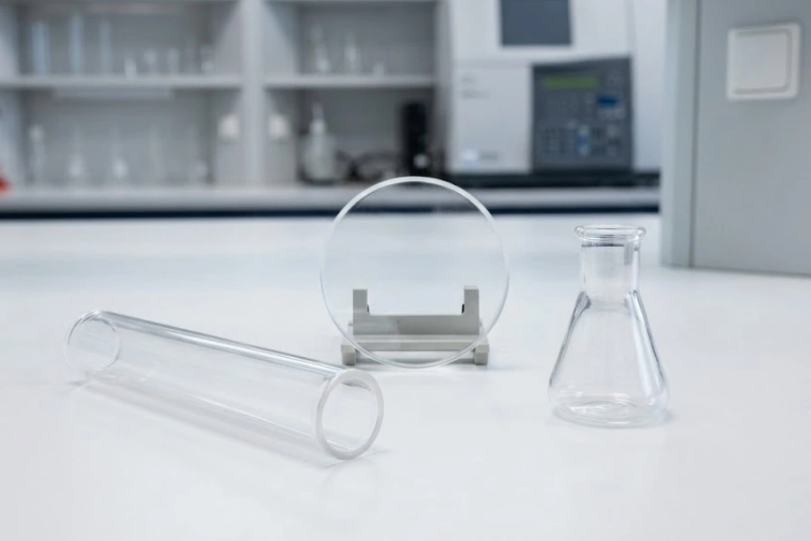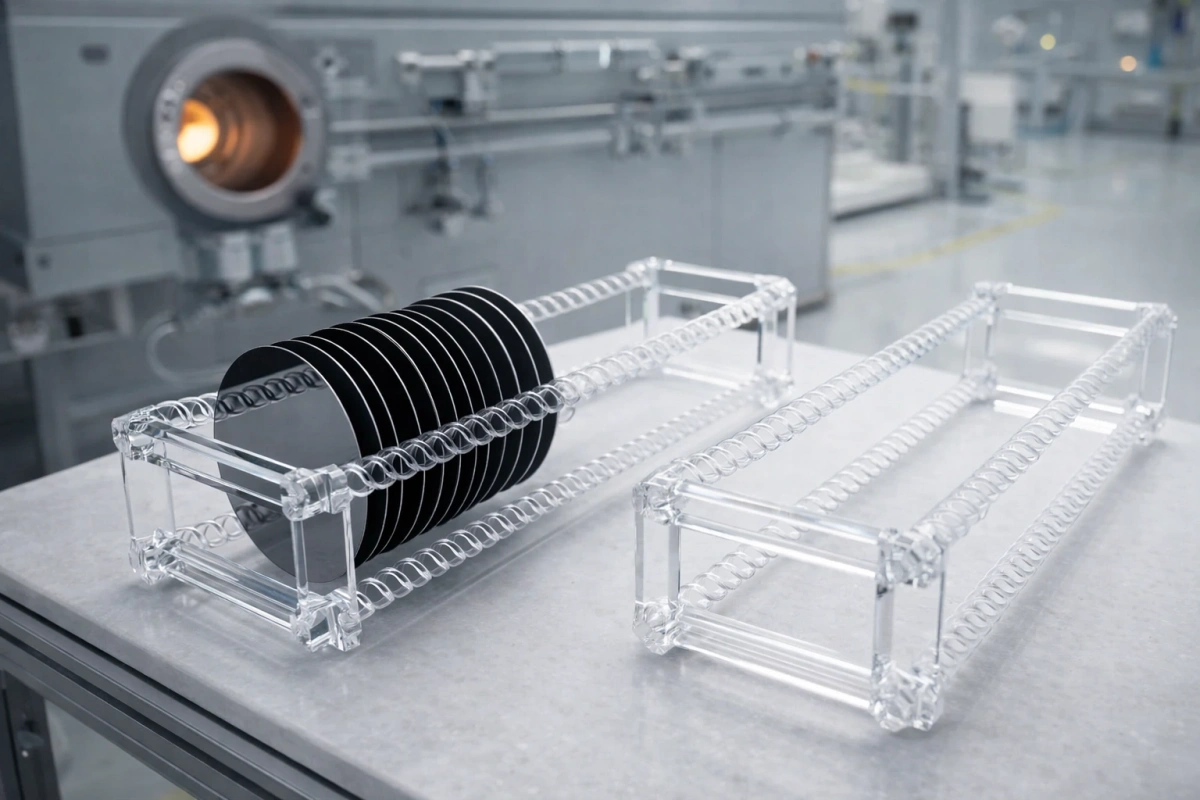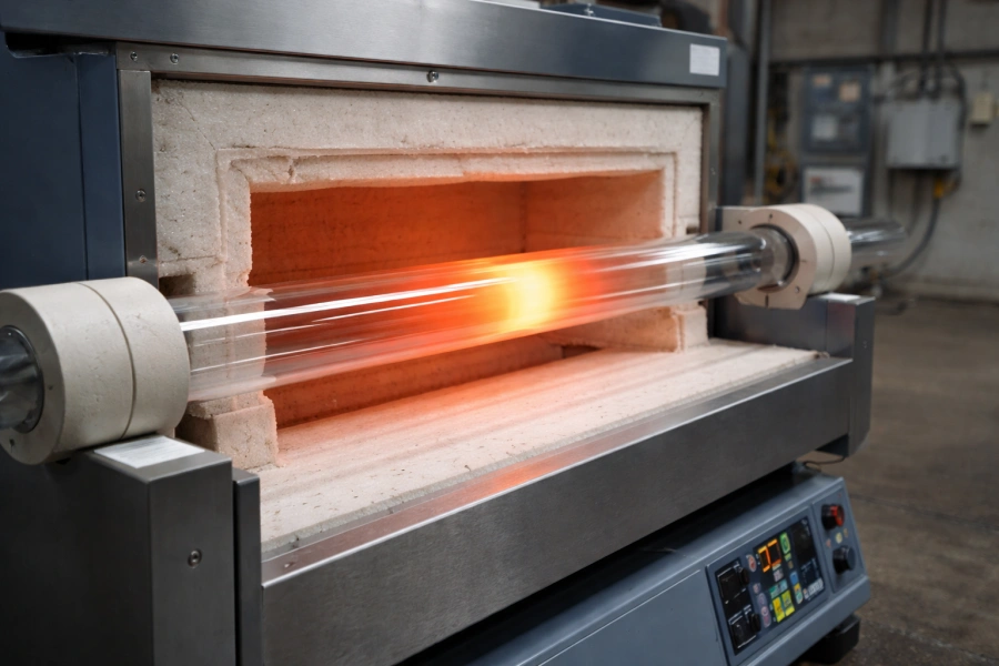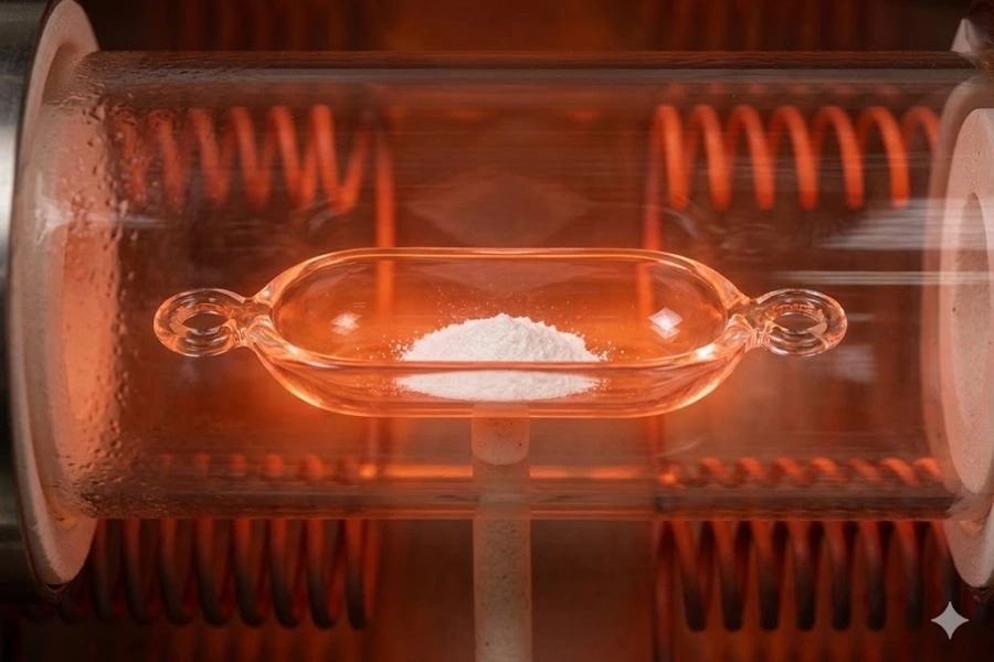
Imprecise specifications waste time, trigger costly remakes, and compromise measurement accuracy. Rigorous quartz part customization solves all three problems before production begins.
Quartz components serve as the functional backbone of laboratory instruments ranging from UV-Vis spectrometers to tube furnaces and ICP-OES systems. Each application category imposes a distinct set of dimensional, optical, thermal, and chemical requirements that generic off-the-shelf parts simply cannot fulfill. This article provides a complete technical framework — covering material selection, surface quality grading, dimensional tolerancing, thermal performance, chemical compatibility, purity classification, and drawing documentation — so that every specification submitted to a manufacturer is complete, unambiguous, and fit for purpose.
Across laboratory disciplines, the consequence of under-specified quartz components is consistently the same: instruments underperform, experiments yield non-reproducible data, and replacement cycles shorten unnecessarily. The following sections address each technical dimension in the precise order that a specification engineer would evaluate them, building from foundational material decisions through to final documentation standards.

Why Laboratory Instruments Demand a Higher Level of Precision in Quartz Components
Compared with general industrial applications, laboratory instruments operate within measurement windows that are extraordinarily narrow. A UV-Vis spectrophotometer, for example, monitors absorbance changes at the level of milliabsorbance units; a quartz window with surface scatter equivalent to just 0.5% of the incident beam introduces systematic error that invalidates quantitative results. Similarly, a tube furnace quartz tube with wall thickness varying by more than 1 mm across its length produces radial thermal gradients that alter crystal growth kinetics in materials research experiments. Furthermore, ICP-MS systems operating at sub-ppb detection limits can be compromised by metallic contamination leaching from an inadequately specified quartz torch tube — contamination that originates not from the sample matrix but from the quartz component itself.
The distinction between laboratory-grade and general industrial quartz parts does not lie in the base material alone. It lies in the tolerance stack — the combined effect of dimensional variation, surface quality deviation, optical inhomogeneity, and purity fluctuation — that accumulates across all specification parameters simultaneously. In general industrial settings, individual deviations of several millimetres or a few percentage points of optical scatter are operationally acceptable; in laboratory instruments, those same deviations invalidate the measurement entirely. Consequently, every parameter in a laboratory quartz specification carries functional weight, and omitting even a single dimension risks receiving a component that passes visual inspection yet fails in service.
Material Selection in Quartz Part Customization for Laboratory Applications`
Material selection sits at the apex of the specification hierarchy because every downstream parameter — surface quality, transmission range, thermal resistance — is constrained by the base material chosen. Two primary material classes are available for laboratory quartz part customization, and selecting the wrong one cannot be corrected by downstream processing or tight tolerancing.
Fused Quartz vs Synthetic Fused Silica: Understanding the Performance Divide
The two materials share the same chemical formula — SiO₂ — yet differ fundamentally in origin, microstructure, and optical behavior. Cuarzo fundido is produced by melting naturally occurring quartz crystals at temperatures exceeding 1,700 °C; the resulting glass retains trace impurities from the source mineral and contains a measurable population of micro-bubbles and refractive-index striations.
Sílice fundida sintética, by contrast, is manufactured via chemical vapour deposition (CVD) or flame hydrolysis of ultra-pure silicon tetrachloride (SiCl₄). This process yields a material with SiO₂ purity exceeding 99.9999% and an internal homogeneity — quantified as refractive index variation Δn — as low as 1 × 10⁻⁶ across the full aperture. Bubble class for synthetic material is typically Class 0 per ISO 10110-3, meaning zero bubbles larger than 0.03 mm are permissible in the clear aperture.
For thermal processing tubes, containment vessels, and structural quartz components where optical transmission is not measured through the part, fused quartz at 99.9% SiO₂ purity is technically sufficient and cost-effective. Wherever wavelength-resolved optical measurement passes through the quartz — windows, cuvettes, flow cells, prisms — synthetic fused silica is the correct baseline.
Fused Quartz vs Synthetic Fused Silica: Key Parameters
| Parámetro | Cuarzo fundido | Sílice fundida sintética |
|---|---|---|
| SiO₂ Pureza (%) | 99.9 | ≥ 99.9999 |
| Refractive Index Homogeneity (Δn) | ~5 × 10⁻⁶ | ≤ 1 × 10⁻⁶ |
| Bubble Class (ISO 10110-3) | Class 2–3 | Class 0 |
| Impurezas metálicas | ppm level | ppb level |
| Applicable Wavelength Range (nm) | 260–3,500 | 150–3,500 |
| Aplicación típica | Tube furnaces, vessels | Optical windows, cuvettes, flow cells |
OH Content as a Specification Variable Across UV, Visible and Infrared Ranges
Hydroxyl (OH) content is the single most consequential compositional variable for optical performance in the UV and infrared spectral regions, yet it is omitted from the majority of laboratory quartz specifications submitted to manufacturers.
High-OH material (typically 800–1,200 ppm) transmits efficiently through the deep ultraviolet, with absorption edge at approximately 165 nm; this makes it the standard choice for UV-Vis spectrophotometry, fluorescence spectroscopy, and any application operating between 170 nm and 400 nm. However, high-OH silica exhibits strong absorption bands centered at 1.38 μm, 2.22 μm, and 2.73 μm, which render it entirely unsuitable for near-infrared (NIR) and mid-infrared (MIR) transmission measurements. Low-OH material (< 10 ppm) eliminates those absorption bands, making it the correct specification for NIR spectrometers operating in the 1–5 μm range and for Raman systems using 1,064 nm excitation.
OH content is measured non-destructively by Fourier Transform Infrared Spectroscopy (FTIR), with the peak absorbance at 3,673 cm⁻¹ serving as the primary quantification band. Manufacturers should be asked to include FTIR-measured OH content on the material certificate for every optical-grade quartz order, expressed in parts per million by weight (ppm wt).
OH Content Specification by Spectral Application
| Aplicación | OH Content Specification | Longitud de onda (nm) |
|---|---|---|
| Espectrofotometría UV-Vis | High-OH: 800–1,200 ppm | 185–900 |
| Fluorescence Spectroscopy | High-OH: 800–1,200 ppm | 200-700 |
| Deep UV Lithography / DUV | High-OH: ≥ 1,000 ppm | 193–248 |
| NIR Process Spectrometry | Low-OH: < 10 ppm | 1,000–2,500 |
| Raman (1,064 nm excitation) | Low-OH: < 10 ppm | 900–1 200 |
| Thermal / Structural (non-optical) | Not critical | N/A |
Dimensional and Optical Specifications for Quartz Part Customization in Optical Instruments
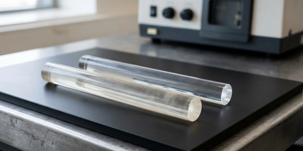
Among all laboratory quartz component categories, optical parts carry the most complex and interdependent specification requirements. A single quartz window in a fluorescence spectrometer must simultaneously satisfy five or more independently measured parameters — surface quality, flatness, parallelism, transmission, and coating — each of which can independently cause instrument failure if not specified. The sections below address each parameter in the sequence a metrologist would evaluate them, from surface-level attributes through to bulk optical performance.
Surface Quality Standards Referenced in Laboratory Optical Quartz Components
Surface quality in optical quartz is governed by two international standard systems that assign numerical grades to surface imperfections, and selecting the correct system — and the correct grade within it — requires understanding what the numbers actually measure.
MIL-PRF-13830B, the most widely referenced standard in North American and international photonics procurement, expresses surface quality as a two-number code: Rascar y cavar, such as 40-20 or 20-10. The first number (scratch designation) is not a direct dimensional measurement but an appearance-based comparison against reference scratches of known width; a scratch designation of 20 corresponds to a maximum allowable scratch width of approximately 20 μm. The second number (dig designation) represents the diameter of allowable point defects in units of 1/100 mm; a dig of 10 means no surface pit exceeding 0.10 mm is acceptable within the clear aperture.
ISO 10110-5 provides an alternative framework that expresses surface imperfections in terms of total scratch length and maximum individual scratch width, allowing direct dimensional comparison. For precision laboratory instruments, 10-5 (MIL) or ISO grade N1 represents the practical upper threshold of what is achievable in production quantities for flat optical elements; grades tighter than 10-5 require 100% individual inspection and are reserved for laser damage-sensitive applications. Fluorescence spectrometers typically accept 20-10; UV-Vis photometers may function adequately with 40-20 in the beam path if scattered light baffling is adequate.
It is critically important to communicate that mechanical polishing to a visually smooth finish does not guarantee optical surface quality grade compliance. An optically polished surface must be verified interferometrically and inspected under a calibrated, collimated light source against reference standards; a visual inspection alone is insufficient for any application requiring surface quality better than 80-50. Inspection documentation — typically a photograph of the surface under dark-field illumination alongside the reference standard — should be requested as part of the acceptance package for any quartz optical component specified at 20-10 or better, as it provides an objective record that the surface quality was verified by the manufacturer before shipment rather than assumed during production.
Surface Quality Grade Selection by Application
| Instrument Type | Recommended Surface Quality (MIL) | ISO 10110-5 Equivalent |
|---|---|---|
| Tube furnace viewport | 80-50 | N4 |
| UV-Vis spectrophotometer window | 40-20 | N2 |
| Fluorescence spectrometer cell | 20-10 | N1 |
| Laser output window (< 1 W/cm²) | 20-10 | N1 |
| High-power laser window (> 1 W/cm²) | 10-5 | < N1 |
| Raman collection optic | 10-5 | < N1 |
Surface Flatness and Parallelism Requirements for Spectroscopic and Flow Cell Applications
Surface flatness and parallelism are geometrically distinct parameters that must be specified independently, as each governs a different failure mode in optical measurement.
Planitud quantifies the deviation of a surface from an ideal plane, expressed in units of wavelength λ (where λ = 632.8 nm by convention). A flatness specification of λ/4 means the peak-to-valley deviation across the clear aperture does not exceed 158 nm. In practice, λ/10 flatness is the minimum standard for any quartz component in a collimated beam path, as wavefront distortion introduced by a λ/4-flat window adds approximately λ/4 of optical path difference per pass, which in interferometric or Fourier-transform instruments accumulates to a resolvable spectral artefact. Flatness is measured on a phase-shifting Fizeau interferometer; manufacturers should provide a flatness map, not merely a pass/fail statement.
Paralelismo quantifies the angular deviation between the two polished faces of a plate or window. In a flow cell for HPLC or stopped-flow measurements, a parallelism error of just 10 arc-seconds across a 10 mm optical path introduces a lateral beam displacement of approximately 0.5 μm, sufficient to produce a measurable baseline drift across a wavelength scan. For flow cells with optical path lengths of 1–10 mm, parallelism should be specified at ≤ 5 arc-seconds; for standard transmission windows, 1–2 arc-minutes is generally acceptable.
Wavefront distortion (WFD), the transmitted equivalent of reflected flatness, must be specified for components operating in transmission. WFD is distinct from surface flatness; it accounts for contributions from both surface geometry and bulk refractive index inhomogeneity. For single-pass transmission windows in collimated beams, WFD ≤ λ/4 per 25 mm aperture is a practical specification threshold. In double-pass configurations — such as retroreflector-based absorption cells or Michelson interferometer arms — the WFD contribution doubles per transit, so the specification must be tightened to ≤ λ/8 per 25 mm aperture to maintain equivalent system wavefront quality. Measurement of WFD requires a transmitted wavefront interferometer (TWI) rather than the standard surface interferometer used for flatness, and the test wavelength used during measurement must match the application wavelength or be reported with a dispersion correction.
Flatness and Parallelism Specification by Application
| Aplicación | Flatness (reflected) | Paralelismo | WFD (transmitted) |
|---|---|---|---|
| General viewport window | λ/4 | ≤ 5 arc-min | Not critical |
| UV-Vis transmission cell | λ/10 | ≤ 2 arc-min | ≤ λ/4 |
| Fluorescence cuvette | λ/10 | ≤ 1 arc-min | ≤ λ/4 |
| HPLC/stopped-flow cell (1–10 mm) | λ/10 | ≤ 5 arc-sec | ≤ λ/10 |
| Laser beam-splitter substrate | λ/20 | ≤ 10 arc-sec | ≤ λ/10 |
| Interferometer reference flat | λ/20 | ≤ 5 arc-sec | ≤ λ/20 |
Transmission Range Specifications and Coating Requirements for Quartz Optical Windows
Transmission range and coating requirements constitute the final functional layer of an optical quartz specification and are the parameters most directly linked to whether the component performs its measurement role. Specifying transmission range without referencing a minimum transmittance value, or specifying a coating without defining its target wavelength band, produces a technically incomplete document that no responsible manufacturer can commit to.
Transmission specifications should follow the format: "Transmittance ≥ T% at wavelength range λ₁–λ₂ nm, measured at normal incidence on an uncoated surface of thickness t mm". For example, a 2 mm thick synthetic fused silica window for UV-Vis work would be specified as "Transmittance ≥ 90% at 200–2,500 nm, uncoated, 2 mm thickness, normal incidence." This format is unambiguous because it separates material bulk transmission from surface reflection losses. An uncoated fused silica surface exhibits approximately 3.5% Fresnel reflection1 per surface (refractive index ~1.46 at 589 nm), resulting in a two-surface total reflection loss of ~6.9%, which is independent of material quality and must not be conflated with bulk absorption.
Anti-reflection (AR) coatings reduce per-surface reflection to below 0.5% across the design bandwidth and should be specified whenever stray light suppression or photon collection efficiency is critical. AR coatings must be specified by: target wavelength band (e.g., 250–450 nm), maximum residual reflectance (e.g., ≤ 0.5% per surface), substrate (synthetic fused silica), and environmental durability class per MIL-C-14806A if the component is exposed to humidity or abrasive cleaning. Hydrophobic coatings applied to flow cell internal surfaces reduce protein adsorption and improve washout efficiency in biochemical applications; these must be specified separately from AR coatings, as they are applied to the fluid-contact face, not the optical-input face.
AR Coating Specification Parameters
| Parámetro | Specification Format | Ejemplo |
|---|---|---|
| Target wavelength band (nm) | λ₁–λ₂ nm | 250–450 nm |
| Max residual reflectance (%) | ≤ R% per surface | ≤ 0.5% per surface |
| Substrate material | Material + grade | Synthetic fused silica, low-OH |
| Durability class | MIL-C-14806A class | Class A (moderate abrasion) |
| Estabilidad térmica (°C) | Up to T°C | Up to 300 °C |
Dimensional Tolerances and Thermal Specifications within Quartz Part Customization for Tube Furnaces
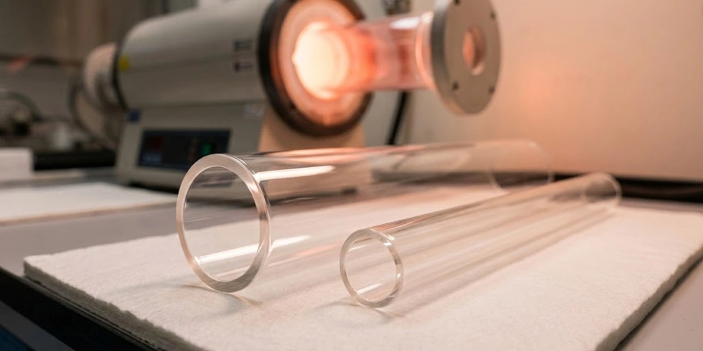
Thermal processing quartz tubes represent the highest-volume customized quartz part category in research laboratories, yet specification sheets submitted for these components are frequently incomplete in their dimensional tolerancing and entirely absent in their thermal performance requirements. Dimensional errors in tube furnace quartz tubes propagate directly into thermal field non-uniformity, sealing failures, and premature tube fracture — all of which disrupt long-duration experiments at critical cost.
Wall Thickness Uniformity, Outer Diameter and Length Tolerances in Laboratory Quartz Tubes
The geometry of a cylindrical quartz tube must be specified across four independent dimensions: outer diameter (OD), inner diameter (ID), length (L), and wall thickness uniformity (ΔW). Each dimension carries a distinct functional consequence, and tolerances on all four must appear in the specification.
Tolerancia OD governs the fit between the tube and the furnace bore, flange clamps, or end-cap assemblies. Standard laboratory tube furnaces are designed for tubes of OD 25, 38, 50, 60, or 80 mm; a tube manufactured at OD 50.8 ± 0.5 mm may bind in a furnace housing designed for ≤ 50.5 mm or may allow convective bypass if the annular gap exceeds 0.5 mm. The appropriate OD tolerance for friction-fit or seal-fit installations is ± 0.3 mm; for loose-fit insertion into a furnace without end sealing, ± 0.5 mm is generally acceptable. ID tolerance is independently critical because it controls the internal gas flow cross-section and the clearance for sample boats or substrates; for CVD and oxidation processes where substrate diameter is fixed, ID tolerance should be specified at ± 0.3 mm minimum.
Wall thickness uniformity (ΔW) is the most frequently omitted and most functionally consequential dimensional parameter for tube furnace applications. A tube with nominal wall thickness of 2.5 mm but ΔW of ± 1.0 mm produces a radial thermal gradient of approximately 8–12 °C per millimetre of wall thickness variation at 1,100 °C operating temperature; this gradient is sufficient to induce differential thermal expansion stresses that initiate micro-cracking within 20–50 thermal cycles. ΔW should be specified at ≤ ± 0.3 mm for research-grade tube furnace applications. Length tolerance of ± 1.0 mm is typically adequate for standard furnace tube installations, though end-cap compression fittings that rely on axial registration may require ± 0.5 mm.
End-face finishing is a specification dimension that directly governs sealing performance. Flat-cut unground ends are acceptable for open-ended, non-sealing tube furnace configurations; ground-flat ends (Ra ≤ 1.6 μm) are required for O-ring face seal assemblies; optically polished ends (Ra ≤ 0.4 μm) are required for compression glass-to-metal seals and high-vacuum flanging. End-face perpendicularity to the tube axis — quantified as the angular deviation between the end-face plane and the tube axis — should also be specified for sealing applications; a deviation exceeding 0.3° on a 50 mm OD tube creates an elliptical contact perimeter that prevents uniform O-ring compression and generates persistent micro-leak channels. Both Ra value and perpendicularity tolerance should appear on the engineering drawing as explicit dimensional callouts, not as verbal notes.
Dimensional Tolerance Reference for Laboratory Quartz Tubes
| Dimensión | Tolerancia estándar | Tolerancia de precisión | Functional Impact |
|---|---|---|---|
| Outer Diameter (OD) (mm) | ± 0.5 | ± 0,3 | Furnace bore fit, seal engagement |
| Inner Diameter (ID) (mm) | ± 0.5 | ± 0,3 | Sample clearance, gas flow area |
| Wall Thickness Uniformity ΔW (mm) | ± 0.5 | ± 0,3 | Radial thermal gradient |
| Longitud (mm) | ± 1.0 | ± 0.5 | End-cap registration |
| End-Face Roughness Ra (μm) | ≤ 1.6 (ground) | ≤ 0.4 (polished) | Sealing integrity |
Thermal Shock Resistance and Maximum Service Temperature as Specification Parameters
Thermal performance specifications for quartz tubes are not material constants that can be assumed; they must be explicitly stated as functional requirements because they constrain the manufacturing method and determine whether standard-grade or premium-grade raw material is required.
Maximum service temperature must be specified as two separate values: the continuous operating temperature (the temperature the tube sustains indefinitely in steady-state) and the peak transient temperature (the maximum temperature experienced during ramp-up or process excursions). For standard fused quartz, the continuous service limit is 1,100 °C and the short-term peak limit is 1,250 °C; above 1,250 °C, viscous deformation (sagging) begins within hours for unsupported horizontal tubes longer than 600 mm. High-purity synthetic fused silica tubes, with SiO₂ ≥ 99.99%, exhibit slightly improved deformation resistance at 1,200–1,300 °C and are mandatory for CVD, LPCVD, and oxidation furnace applications where metallic contamination from tube impurities would compromise device performance.
Resistencia al choque térmico is quantified by the maximum permissible ΔT (temperature differential) that the tube can withstand without fracture initiation. For fused quartz, the theoretical thermal shock resistance is approximately 1,000 °C (ΔT), significantly superior to borosilicate glass (ΔT ~120 °C), because fused quartz's coefficient of thermal expansion (CTE) is only 0.55 × 10⁻⁶ /°C. However, this theoretical resistance degrades sharply in the presence of pre-existing surface micro-flaws. A tube with surface scratches from improper handling may fracture at ΔT as low as 300–400 °C. Consequently, specifications for tubes used in rapid thermal processing (RTP) or flash annealing systems — where ramp rates of 50–100 °C/second are common — must include a surface quality requirement (Ra and visual inspection class) in addition to the thermal performance statement. Thermal cycling endurance data, where available from the manufacturer, should be requested for tubes used in experiments requiring more than 500 thermal cycles per year; fatigue-initiated fracture from repetitive thermal stress is a well-documented failure mode for quartz tubes that are otherwise operating within nominal single-cycle ΔT limits, particularly for tubes with OD-to-wall-thickness ratios exceeding 20:1.
Thermal Performance Specifications for Quartz Tubes
| Parámetro | Standard Fused Quartz | High-Purity Synthetic Silica (≥99.99%) |
|---|---|---|
| Temperatura de servicio continuo (°C) | 1,100 | 1,200 |
| Temperatura máxima a corto plazo (°C) | 1,250 | 1,300 |
| CTE (×10-⁶ /°C) | 0.55 | 0.55 |
| Theoretical Thermal Shock ΔT (°C) | ~1,000 | ~1,000 |
| Metallic Impurity Level | ppm | ppb |
| Required Application | General tube furnaces | CVD, LPCVD, epitaxy, oxidation |
Quartz Part Customization Addressing Chemical Compatibility in Analytical Instruments
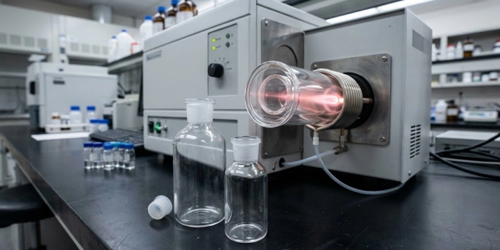
Chemical analysis instruments impose a fundamentally different set of constraints on quartz components compared with optical or thermal applications. In ICP-OES, ICP-MS, and microwave digestion systems, the quartz part is simultaneously a structural element, a fluid conduit, and a thermal barrier — and it must perform all three functions in aggressive acidic environments at elevated temperatures. Quartz part customization for this application category must therefore address geometric precision, chemical surface integrity, and thermal performance as an integrated specification set rather than as independent parameters.
Concentricity and Geometric Tolerances in ICP Torch Tube Specifications
The ICP torch tube is a three-layer coaxial quartz assembly — outer tube, intermediate tube, and inner injector tube — whose performance depends critically on the concentricity and dimensional accuracy of all three components simultaneously. Concentricity failure, not material failure, is the primary cause of ICP plasma instability in analytical practice. The three tubes are held in position by the torch body, which provides radial constraint only at the base; across the 80–100 mm length of the plasma zone, any initial misalignment amplifies as the tubes expand thermally during plasma ignition, making the ambient-temperature concentricity specification the only controllable parameter available at the manufacturing stage.
Concentricidad is defined as the radial offset between the geometric centre of the inner tube and the geometric centre of the outer tube when the assembly is in its operating configuration. In a properly specified ICP torch, this offset should not exceed 0.15 mm across the full length of the plasma zone (typically 50–80 mm from the load coil base). When concentricity exceeds 0.3 mm, the plasma forms asymmetrically, the central channel tilts, and the radial temperature profile becomes non-uniform; this manifests analytically as increased relative standard deviation (RSD) in repeated intensity measurements, with RSD values rising from a normal range of 0.5–1.0% to 3–5% or higher. The inner tube (injector) bore diameter and its concentricity with the outer tube are the two dimensions that most directly control nebuliser gas flow uniformity and aerosol axial injection trajectory.
Torch tube assemblies for different instrument brands are not interchangeable, even when nominal dimensions appear similar. Agilent 5800/5900 series torches use an outer tube OD of approximately 18.5 mm with a 1.0 mm wall; PerkinElmer Avio and Optima series torches use a 19.0 mm outer tube OD with a 1.5 mm wall; Thermo Fisher iCAP series torches use a distinct taper angle at the base. All three dimensions — OD, ID, and taper angle — must be specified against the exact instrument model, and the manufacturer should be provided with either an original torch as a dimensional reference sample or a full GD&T drawing with concentricity callouts per ASME Y14.52.
The end-face finish at the base of the outer tube, where it interfaces with the torch body O-ring, requires Ra ≤ 0.8 μm to achieve the sealing integrity necessary for argon gas pressures of 10–20 L/min without leakage. Leakage at this interface dilutes the plasma gas stream, lowers plasma temperature, and induces spectral background fluctuations that degrade detection limits.
ICP Torch Tube Dimensional Specification Reference
| Dimensión | Specification Range | Tolerancia | Functional Consequence of Deviation |
|---|---|---|---|
| Outer Tube OD (mm) | 17.0–22.0 (instrument-specific) | ± 0,1 | Torch body fit, O-ring seal |
| Outer Tube Wall Thickness (mm) | 1.0–1.5 | ± 0,1 | Thermal stress resistance |
| Inner Tube (Injector) ID (mm) | 1.5–2.5 (instrument-specific) | ± 0,05 | Gas flow velocity, aerosol trajectory |
| Concentricity (OD to OD) (mm) | - | ≤ 0.15 | Plasma symmetry, RSD |
| Base End-Face Roughness Ra (μm) | - | ≤ 0,8 | Argon gas seal integrity |
Acid Resistance and Surface Treatment Specifications for Quartz Digestion Vessels
Quartz digestion vessels — used in microwave digestion, open-vessel wet acid digestion, and high-pressure bomb digestion — are exposed to concentrated mineral acids including HNO₃, HCl, H₂SO₄, HF, and aqua regia at temperatures ranging from 150 °C (microwave) to 300 °C (high-pressure). While fused quartz is chemically resistant to all of these acids with the exception of hydrofluoric acid, the functional lifetime of a quartz digestion vessel is governed primarily by its internal surface condition, not by its bulk chemical resistance.
HF attacks the SiO₂ network at a rate that is strongly surface-area-dependent; a polished internal surface with Ra ≤ 0.4 μm presents a minimal reactive area, while a ground or mechanically abraded interior with Ra of 1.5–3.0 μm exposes 4–8 times the effective surface area per unit geometric area. Consequently, quartz digestion vessels for trace metal analysis — where contamination from vessel dissolution at ppb levels is analytically significant — must specify internal surface Ra ≤ 0.4 μm with fire-polished or precision-ground and chemically re-polished finish. At this surface finish level, silica dissolution in 70% HNO₃ at 180 °C is typically < 0.1 μg/cm²/hour, which is acceptable for ICP-MS blanks at the 1 ppb reporting level.
Thermal shock is a separate concern for microwave digestion vessels because the energy delivery in a microwave cavity is volumetric rather than surface-applied; temperature rises of 80–120 °C within 60–90 seconds are common in high-power microwave digestion protocols. Vessels intended for microwave digestion must therefore specify both the maximum operating temperature and the maximum permissible ramp rate (typically 10–15 °C/second for fused quartz vessels without pre-existing surface damage), in addition to the wall thickness and its uniformity. Vessel wall thickness for standard microwave digestion tubes (25–50 mL capacity) is typically 2.0–3.0 mm; wall uniformity ≤ ± 0.3 mm is required to prevent stress concentration during rapid heating.
Quartz Digestion Vessel Specification Parameters
| Parámetro | Especificación estándar | Trace-Metal Grade Specification |
|---|---|---|
| Internal Surface Ra (μm) | ≤ 1.6 | ≤ 0.4 |
| Espesor de pared (mm) | 2.0–3.0 | 2.5 ± 0.3 |
| Max Operating Temperature (°C) | 200 | 250 |
| Max Ramp Rate (°C/s) | 5 | 10-15 |
| HF Compatibility | Limitado | No recomendado |
| Applicable Digest Method | Open vessel, conventional | Microwave, high-pressure |
Gas Tightness and End Finishing Requirements Across Laboratory Quartz Assemblies
End finishing and sealing specifications apply across all three primary application categories discussed above, yet they are rarely addressed as a coherent parameter group in laboratory quartz procurement. Overlooking these specifications generates the most common class of field failure: components that meet all optical, thermal, or chemical parameters but leak at the joint interface.
-
Flange end configurations and KF/ISO/CF compatibility
Standard laboratory quartz tube systems interface with ultra-high-vacuum (UHV) and process vacuum hardware through one of three flange systems: KF (Klein Flange, also called QF), ISO, or CF (ConFlat). KF flanges (KF16, KF25, KF40, KF50) use an elastomeric O-ring captured in a centering ring and are suitable for pressures down to 10⁻⁶ mbar; the mating quartz end-face must be flat to within ± 0.1 mm and have Ra ≤ 1.6 μm. ISO flanges are used for larger bore systems (ISO63, ISO100, ISO160) and have similar surface finish requirements. CF (ConFlat) flanges use a knife-edge metal gasket and are suitable for UHV to 10⁻¹¹ mbar; the mating surface must be ground to a flatness of ± 0.05 mm and Ra ≤ 0.4 μm to avoid leak paths across the copper gasket contact line. Specifying the flange type and size in dimensional nomenclature (e.g., "KF40 end flange, bonded, DN40") prevents ambiguity between internal and external bore sizing conventions.
-
O-ring groove and face-seal finishing requirements
When quartz tubes are sealed against compression O-rings in the axial (face seal) configuration — as is common in tube furnace end-cap assemblies — the end-face Ra value directly governs the sealing capability. An end-face Ra of ≤ 0.8 μm is the minimum requirement for reliable static sealing against a 70-Shore-A silicone or Viton O-ring at pressures up to 2 bar positive or 10⁻³ mbar negative. Above this Ra threshold, the O-ring cannot fully conform to the surface profile under the available compression force, and micro-channels persist across the seal interface. End-face perpendicularity to the tube axis must also be specified; an angular deviation of > 0.5° in a 50 mm OD tube creates a gap at the seal perimeter of approximately 0.43 mm at full O-ring compression, sufficient to allow leakage at pressures above 0.5 bar. Additionally, the contact width of the O-ring groove — typically 60–70% of the O-ring cross-section diameter — must be dimensioned on the drawing when an integrated groove is machined into the end face rather than captured in a separate metallic centering ring, as groove width directly controls O-ring compression percentage and hence sealing force.
-
Helium leak testing as an acceptance specification
For quartz assemblies that must maintain vacuum integrity below 10⁻⁶ mbar — including gas-tight furnace tubes, ICP torch housings, and sealed flow cell bodies — helium mass spectrometer leak testing3 should be specified as a mandatory acceptance criterion. The standard laboratory acceptance threshold for a sealed quartz assembly is a He leak rate of ≤ 1 × 10⁻⁹ mbar·L/s (equivalent to < 1 × 10⁻⁹ Pa·m³/s). This specification must appear on the component drawing as an acceptance test requirement, not merely as a general quality note, so that it is traceable in the manufacturing quality record.
Collectively, end finishing and sealing specifications form the connection layer between a precisely dimensioned quartz component and the instrument system it serves; without explicit sealing specifications, dimensional accuracy is necessary but not sufficient for field reliability.
Purity Grades and Contamination Control Specifications Embedded in Quartz Part Customization
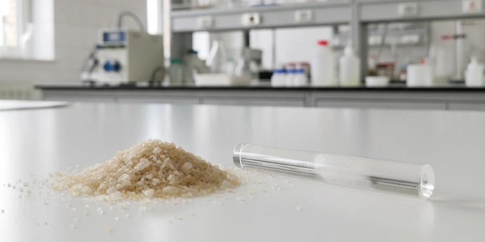
Beyond OH content and base material selection, absolute SiO₂ purity and trace metallic contamination represent an independent specification dimension that is orthogonal to optical, thermal, and geometric performance. In trace analytical laboratories and semiconductor research environments, contamination introduced by the quartz part itself is a primary source of measurement error — and it is a source that no amount of careful sample preparation can eliminate if the component specification is silent on purity.
SiO₂ purity grades are conventionally expressed as four-nines (99.99%), five-nines (99.999%), or six-nines (99.9999%). For the majority of thermal and optical laboratory applications, 99.9% purity (three-nines) is the standard commercial baseline. However, for high-temperature semiconductor-related experiments — diffusion, oxidation, LPCVD — where trace metals from the tube wall diffuse into the substrate at elevated temperatures, 99.99% (four-nines) is the minimum acceptable purity, and the specification must include a Certificate of Conformance (COC) reporting individual metallic impurities by element. The critical contaminant elements are Al, Fe, Ca, Na, Ti, and Cr at sub-ppm concentrations; at 1,100 °C, Fe diffuses into silicon at a rate that is detectable by DLTS (Deep Level Transient Spectroscopy) at concentrations as low as 10¹² atoms/cm³, corresponding to a tube wall Fe content of less than 0.1 ppm.
For ICP-MS trace element analysis at sub-ppb reporting levels, the quartz components in the sample introduction pathway — torch tube, spray chamber, and transfer line — must be specified at five-nines purity (99.999%) and must carry a COC reporting Al, Fe, Ca, Na, Mg, K, Zn, Pb, and Cr at < 10 ppb (ng/g) levels. At these purity grades, the measurement contribution from component dissolution during normal operation falls below the method detection limit for most elements at the 0.1 ppb reporting level.
Cleanroom packaging requirements are a purity specification, not merely a handling preference. A five-nines purity quartz tube delivered in an unsealed plastic bag without nitrogen purge will accumulate particulate contamination at a rate of approximately 500–1,000 particles/cm² per day in a Class 10,000 (ISO 7) environment. Components specified for trace analytical or semiconductor applications must require Class 1,000 (ISO 6) or better cleanroom bagging in sealed, nitrogen-purged low-density polyethylene (LDPE) bags, with the bag interior surface pre-cleaned by ultrapure water (≥ 18.2 MΩ·cm) rinse. The packaging specification should appear on the engineering drawing under the "Notes" block, not as a verbal instruction, to ensure it is captured in the quality record. For the most contamination-sensitive applications — such as quartz components used in the sample introduction pathway of an ICP-MS system operating at sub-ppt detection limits — double-bagging with an inter-bag nitrogen flush, followed by storage in a sealed, humidity-controlled container, is the appropriate minimum standard.
SiO₂ Purity Grade by Laboratory Application
| SiO₂ Purity Grade | Metallic Impurity Level | Required COC? | Applicable Laboratory Application |
|---|---|---|---|
| 99.9% (3N) | ppm level | No | General tube furnaces, structural components |
| 99.99% (4N) | sub-ppm (< 1 ppm) | Yes — element list | Semiconductor diffusion, oxidation, LPCVD |
| 99.999% (5N) | ppb level (< 10 ppb) | Yes — full ICP-MS scan | ICP-MS sample introduction, trace metals analysis |
| 99.9999% (6N) | sub-ppb (< 1 ppb) | Yes — full ICP-MS + GDMS | Ultratrace semiconductor research, reference standards |
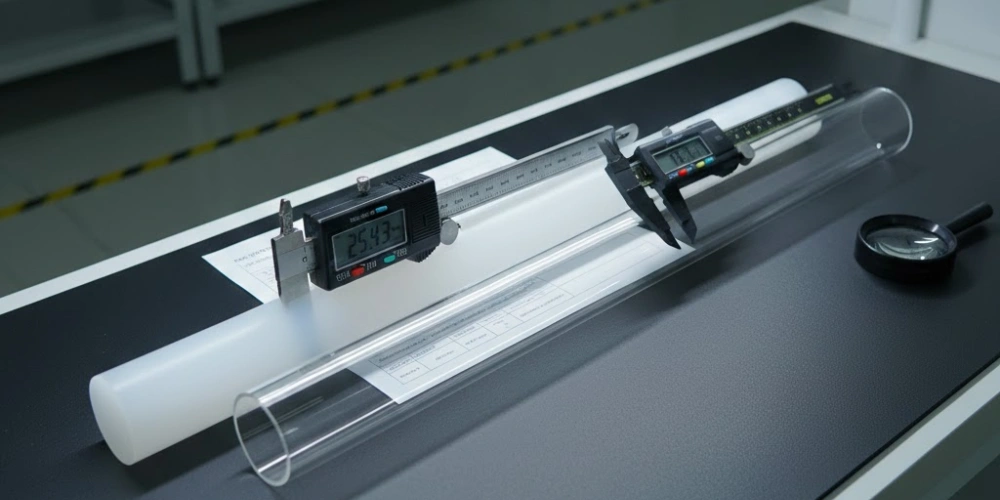
Dimensional Drawing Standards and Documentation Required for Custom Quartz Orders
Specification documentation is the interface between the engineer's intent and the manufacturer's interpretation; ambiguity at this interface is the most preventable cause of non-conforming quartz components. Every parameter discussed in the preceding sections must be expressed in a documentable, verifiable, and legally traceable form before a custom quartz order is placed.
-
Engineering drawing format and file type requirements
Quartz component drawings should be submitted as 2D dimensional drawings in PDF or DXF format, with a 3D STEP file provided as a supplementary reference for complex geometries such as torch tubes, custom flanged assemblies, or non-circular cross-sections. DXF files are preferred over DWG for cross-platform compatibility. PDF drawings must be submitted at a minimum resolution of 300 DPI with all annotation text readable at 100% zoom. STEP files alone are not acceptable as the primary specification document because they convey nominal geometry without tolerances; a STEP model with no tolerance information is dimensionally defined to the file resolution (~0.001 mm), which does not reflect the agreed manufacturing tolerance and creates contract ambiguity.
-
GD&T annotation and tolerance callout standards
Geometric Dimensioning and Tolerancing (GD&T) per ASME Y14.5-2018 or ISO 1101:2017 must be used for any quartz component where functional performance depends on geometric relationships between features — concentricity, parallelism, perpendicularity, cylindricity, or flatness. Direct +/- tolerancing alone is insufficient for specifying concentricity in ICP torch tubes, parallelism in optical flow cells, or end-face perpendicularity in sealing flanges because it does not constrain the geometric relationship between features, only the size of individual features in isolation. GD&T callouts for these parameters allow the manufacturer to select the correct measurement method and datum structure, ensuring that what is inspected corresponds to what actually determines functional performance.
-
Specification sheet, COC, and first article requirements
For quartz part customization involving critical laboratory applications, a three-document package is the minimum acceptable quality record: (1) a Specification Sheet listing all functional requirements (material grade, OH content, purity, surface quality, transmission range, coating) in a tabular format with acceptance criteria and test methods; (2) a Certificate of Conformance (COC) confirming that the material used meets the specified purity grade with elemental analysis data; and (3) a First Article Inspection Report (FAIR) for new custom geometries, in which 100% of dimensional callouts on the engineering drawing are measured and recorded against the tolerance. The FAIR serves as the baseline against which all subsequent production lots are compared. Without a FAIR, dimensional drift across production batches is undetectable until instrument failure occurs.
Together, these three documents close the specification loop from design intent through material certification to dimensional verification, and they form the quality traceability chain that laboratory accreditation bodies — including ISO 17025 and GLP programmes — require for consumable component procurement. For recurring orders, the FAIR from the first production lot should be archived and referenced by lot number in all subsequent COCs, creating a longitudinal dimensional record that allows detection of tooling wear or process drift before non-conforming components reach the instrument. In regulated laboratory environments — pharmaceutical QC, environmental reference laboratories, food safety testing — this documentation chain is not a best practice but a compliance requirement, and its absence during an audit constitutes a finding against the laboratory's quality management system.
Conclusión
Accurate quartz part customization for laboratory instruments rests on seven interconnected specification disciplines: material class selection, OH content assignment, surface quality grading, dimensional tolerancing, thermal performance definition, chemical compatibility parameterisation, purity grade specification, and drawing documentation. Each discipline is independently necessary, and none can compensate for deficiencies in another. A component specified with perfect optical surface quality but incorrect OH content will still transmit at the wrong wavelength range; a tube specified at the correct purity grade but without wall thickness uniformity tolerances will still generate thermal gradients that compromise experimental reproducibility. The frameworks, specification tables, and tolerance values provided throughout this article equip engineers and laboratory procurement personnel with the technical vocabulary and parameter ranges needed to produce specifications that are complete, unambiguous, and optimised for the specific instrument application in which the quartz component will serve.
PREGUNTAS FRECUENTES
What is the difference between fused quartz and fused silica in laboratory quartz part customization?
Fused quartz is produced by melting natural quartz crystals and contains trace mineral impurities and micro-bubbles, making it suitable for thermal and structural applications. Fused silica (synthetic fused silica) is manufactured via chemical vapour deposition from ultra-pure precursors, yielding optical homogeneity (Δn ≤ 1 × 10⁻⁶) and SiO₂ purity up to 99.9999%, making it the required material for optical measurement applications in the UV, visible, and NIR spectral ranges.
Why does OH content matter when specifying quartz optical windows or cuvettes?
OH content controls transmission performance at the spectral extremes: high-OH material (800–1,200 ppm) transmits efficiently from 170 nm into the UV, while low-OH material (< 10 ppm) suppresses absorption bands at 1.38 μm and 2.73 μm, enabling NIR and mid-IR transmission. Specifying OH content incorrectly — high-OH for an NIR spectrometer, for example — results in strong absorption artefacts at wavelengths critical to the measurement, which cannot be corrected by calibration.
What surface quality grade should be specified for a quartz flow cell in HPLC or stopped-flow spectroscopy?
Flow cells for HPLC and stopped-flow applications require surface quality of 20-10 (MIL-PRF-13830B) on the optical-input faces, flatness of λ/10 or better, and parallelism ≤ 5 arc-seconds between the two transmission windows. The internal fluid-contact surfaces should be polished to Ra ≤ 0.4 μm to minimise adsorption and facilitate complete washout between injections. These specifications should be stated explicitly on the component drawing rather than assumed under a general "optical grade" label.
How should purity grade and contamination control be specified for quartz tubes used in ICP-MS sample introduction?
Quartz components in the ICP-MS sample introduction pathway should be specified at five-nines purity (99.999% SiO₂) with a Certificate of Conformance reporting Al, Fe, Ca, Na, Mg, K, Zn, Pb, and Cr at < 10 ppb by ICP-MS analysis. Packaging must specify ISO Class 6 (Class 1,000) cleanroom bagging in nitrogen-purged LDPE, with ultrapure water pre-rinse. These purity and packaging requirements should appear as formal specification notes on the engineering drawing to ensure traceability in the quality record.
Referencias:
-
Fresnel reflection describes the partial reflection of light that occurs at an interface between two media of differing refractive indices, producing predictable surface reflection losses calculable from the Fresnel equations. ↩
-
ASME Y14.5 is the American Society of Mechanical Engineers standard governing Geometric Dimensioning and Tolerancing (GD&T), providing the formal symbolic language used to communicate geometric relationships and tolerances on engineering drawings. ↩
-
Helium mass spectrometer leak testing is the most sensitive commercially available method for detecting vacuum leaks in sealed assemblies, capable of resolving leak rates as low as 10⁻¹² mbar·L/s using helium as a tracer gas. ↩