A fraction-of-a-millimeter deviation in geometry, or a single step down in purity grade, is sufficient to compromise an entire high-temperature process. The consequences span from dimensional misfit at assembly to catastrophic melt contamination during operation.
In semiconductor crystal growth, photovoltaic ingot casting, and high-precision laboratory fusion, crucible performance is entirely contingent on how precisely each parameter is defined before manufacturing begins. Geometry, purity, wall thickness, surface condition, structural form, optical character, and thermomechanical behavior each function as an interdependent variable within a tightly constrained system.
Premature crucible failure and melt contamination are almost invariably traceable to parameters that were inadequately specified at the ordering stage. A thorough command of the full parameter landscape is therefore not an academic exercise — it is an operational prerequisite.
Dimensional Specifications in Customized Quartz Crucibles
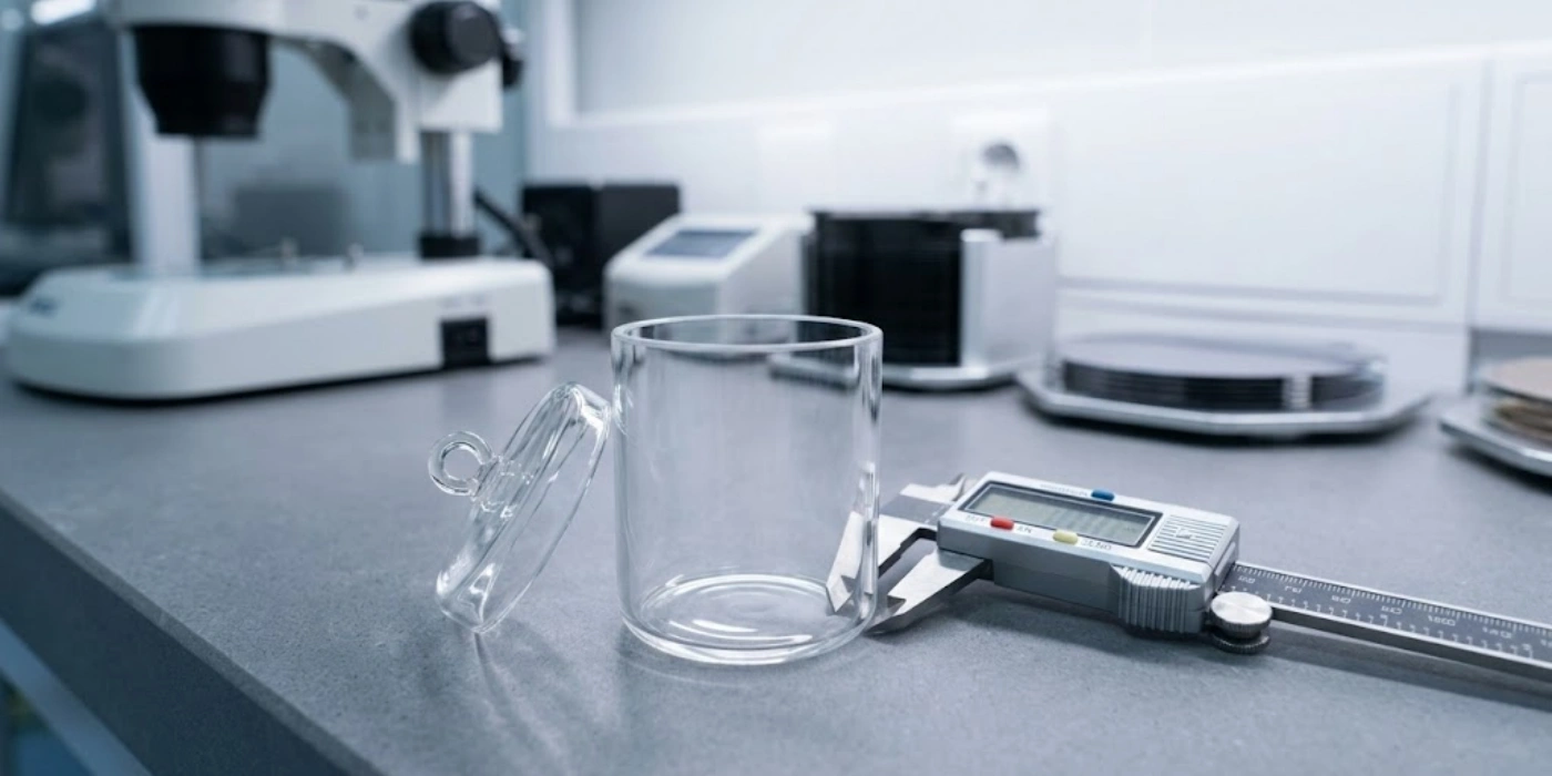
Precise dimensional definition is the starting point for any order of customized quartz crucibles, establishing the geometric envelope within which all other parameters — wall thickness, surface finish, and structural form — must operate. Accordingly, the three primary dimensional attributes and their associated sub-features are addressed first, in order of decreasing geometric scale.
Outer Diameter, Inner Diameter and Depth Tolerances
The three primary dimensions of a quartz crucible — outer diameter (OD), inner diameter (ID), and depth (H) — are geometrically interdependent, and their tolerances cannot be assigned in isolation. OD and ID together determine the nominal wall thickness (t = (OD − ID) / 2), which means that tolerances on both dimensions must be specified simultaneously to avoid producing a crucible with a wall section that falls below the structural minimum or exceeds the thermal design envelope.
For standard cylindrical crucibles used in Czochralski silicon crystal growth, OD tolerances typically range from ±0.5 mm for crucibles below 12 inches zu ±1.0 mm for diameters of 18 inches and above. ID tolerances are held more tightly in most semiconductor-grade applications — commonly ±0.3 mm to ±0.5 mm — because the internal cavity directly contacts the silicon melt and any deviation in internal radius affects melt volume and thermal symmetry. Depth tolerances for standard configurations generally fall within ±1.0 mm to ±2.0 mm, though applications requiring precise melt-level control may demand depth tolerances as tight as ±0,5 mm.
Geometric consistency across a production batch is as critical as the nominal values themselves. Batch-to-batch dimensional variation exceeding 0.8 mm in OD has been documented to cause fit failures in automated crystal pullers, where the crucible seats within a graphite susceptor with virtually no clearance tolerance.
Rim Geometry and Its Effect on Sealing Performance
The rim — the uppermost edge of the crucible — is a dimensional feature that receives disproportionately less attention in specifications yet governs the crucible's sealing integrity, mechanical contact behavior, and compatibility with retaining hardware. Three principal rim profiles are produced in commercial customization: flat-top (planar), rounded-lip, and flanged.
A flat-top rim is the most common configuration, with a face width typically between 3 mm and 8 mm and a flatness tolerance of ≤ 0.2 mm across the full circumference. Deviations in rim flatness can create localized stress concentrations when the crucible is clamped or seated, particularly in sealed furnace systems where uniform contact pressure is required to maintain atmosphere integrity. A rounded-lip profile, with a convex cross-section radius of 1.5 mm to 4.0 mm, is specified in applications where the rim contacts a soft gasket material, as the curved geometry distributes contact stress more evenly and reduces the risk of chipping along the edge.
Flanged rims — where a horizontal shelf extends radially outward from the crucible wall — introduce additional parameters: flange width (typically 5 mm to 20 mm), flange thickness (2 mm to 6 mm), and flange planarity (≤ 0.3 mm). These dimensions must be specified as a coordinated set, since an insufficiently thick flange will deflect under load, negating the dimensional benefit of the flange profile entirely.
Bottom Profile Variations Across Crucible Types
The geometry of the crucible base determines how the crucible seats within its support structure, how thermal energy is conducted from the base upward through the melt, and how mechanical stress distributes across the lowest section of the wall. Three standard base profiles are produced: flat-bottom, round-bottom (hemispherical), and conical (V-bottom).
Flat-bottom crucibles are described by a single additional parameter: base thickness, which typically ranges from 4 mm to 15 mm depending on crucible diameter and the thermal load requirement. Round-bottom crucibles require specification of the internal base radius of curvature (R), which must be equal to or greater than the internal radius of the cylinder to avoid creating a stress-concentrating discontinuity at the wall-to-base junction. In practice, R values between 0.5× and 0.8× of the internal radius are the most frequently specified range.
Conical bases are defined by the included half-angle (α), typically between 30° und 60°, and the apex geometry — whether pointed, flat-truncated, or radius-blended. A truncated apex with a minimum flat diameter of 5 mm bis 10 mm is standard practice to prevent stress fractures at the cone tip during thermal cycling. The base wall thickness at the thinnest section of a conical bottom should not fall below 3 mm for crucibles operating above 1,400°C.
Dimensional Specifications Summary
| Parameter | Small Diameter < 6 in | Medium Diameter 6–14 in | Large Diameter > 14 in |
|---|---|---|---|
| OD Tolerance (mm) | ±0.3 | ±0.5 | ±1.0 |
| ID Tolerance (mm) | ±0.2 | ±0.3 | ±0.5 |
| Depth Tolerance (mm) | ±0.5 | ±1.0 | ±2.0 |
| Rim Flatness (mm) | ≤ 0.1 | ≤ 0.2 | ≤ 0.3 |
| Base Thickness Min (mm) | 3 | 5 | 8 |
| Base Radius Curvature (× internal R) | 0.5-0.8 | 0.5-0.8 | 0.5-0.8 |
Dimensional Tolerances and Industry Standards for Quartz Crucibles
With individual dimensional parameters defined, the next logical consideration is the standardized framework that governs how those tolerances are measured, verified, and accepted — since a parameter without a measurement standard is commercially unenforceable.
SEMI standards provide the most widely applied technical framework for quartz components used in semiconductor manufacturing. SEMI C8 addresses chemical purity requirements for quartz hardware, while SEMI M54 covers fused silica components used in silicon crystal growth environments, specifying both dimensional and contamination requirements. These standards establish minimum acceptance criteria but do not preclude tighter customer-specific tolerances, which take precedence whenever a detailed engineering drawing is submitted.
ISO 3585 governs transparent fused silica laboratory glassware, specifying dimensional tolerances, optical homogeneity, and chemical resistance requirements for fused silica vessels. While ISO 3585 is oriented toward laboratory applications rather than semiconductor-grade crucibles, its tolerance methodology — particularly the concept of Grade A and Grade B dimensional accuracy classes — is frequently referenced in custom quartz fabrication contracts as a baseline when no application-specific standard applies.
The hierarchy between standards and customer-supplied drawings follows a well-established precedent: a dimensioned customer drawing with explicit tolerance callouts overrides manufacturer's standard tolerances in all cases. When a drawing does not specify a tolerance for a given dimension, the applicable fallback is the manufacturer's published standard, not the tightest value in any referenced normative document.
Tolerance Grade Reference
| Parameter | ISO 3585 Grade A | SEMI M54 Baseline | Tight Custom Spec |
|---|---|---|---|
| OD / Major Dimension | ±1% of nominal | ±0,5 mm | ±0,2 mm |
| Wanddicke | ±10% | ±0,5 mm | ±0,2 mm |
| Depth / Height | ±1,5% | ±1,0 mm | ±0,5 mm |
| Rim Flatness (mm) | ≤ 0.5 | ≤ 0.3 | ≤ 0.1 |
| Surface Roughness Ra (μm) | ≤ 1.6 | ≤ 0.8 | ≤ 0.4 |

Purity Grades and Material Composition of Quartz Crucibles
Following the dimensional framework, material purity emerges as the second critical axis of customization — one that operates entirely independently of geometry yet exerts the most decisive influence on crucible performance in contamination-sensitive processes. Purity grade and raw material origin together establish the contamination ceiling for any given application.
The 4N to 9N Purity Scale and What Each Level Means
The purity of fused quartz is expressed as the proportion of silicon dioxide (SiO₂) in the total material composition, denoted by the "N" convention where the number indicates the count of nines in the percentage. 4N denotes 99.99% SiO₂ purity, implying a total impurity content of ≤ 100 ppm by mass. 6N denotes 99.9999% SiO₂, with total impurities at ≤ 1 ppm. At the upper bound, 9N (99.9999999%) represents an impurity ceiling of ≤ 1 ppb and is reserved exclusively for the most demanding semiconductor crystal growth environments.
The practical distinction between these grades lies in the concentration of specific metallic impurities, not merely the aggregate purity figure. Iron (Fe), aluminum (Al), calcium (Ca), sodium (Na), potassium (K), and titanium (Ti) are the primary contaminant species monitored independently. At 4N grade, Fe concentrations may be as high as 5–20 ppm; at 6N grade, Fe is typically held below 0.05 ppm (50 ppb); at semiconductor-grade 9N material, Fe content is controlled to < 5 ppb. These trace concentrations are verified by induktiv gekoppelte Plasma-Massenspektrometrie (ICP-MS)1, the only analytical technique with sufficient detection sensitivity below the 10 ppb threshold.
The selection of purity grade is not arbitrary — it is derived directly from the process requirement. In Czochralski silicon crystal growth, any metallic impurity that dissolves from the crucible wall into the silicon melt at elevated temperature will be incorporated into the growing crystal, where it acts as an electrically active defect center that degrades minority carrier lifetime and reduces device yield. A transition from 4N to 6N crucible material has been documented to reduce metallic contamination in pulled crystal by more than one order of magnitude under equivalent process conditions.
Natural Fused Quartz Versus Synthetic Fused Silica
The two raw material routes for fused quartz production differ fundamentally in their origin, processing chemistry, and resulting impurity profiles. Natural fused quartz is produced by melting high-purity vein quartz or quartzite at temperatures above 1,700°C, typically in electric arc or hydrogen-oxygen fusion furnaces. The source mineral inevitably contains geological impurity signatures — aluminum concentrations in natural quartz feedstock range from 10 ppm to over 200 ppm depending on geological provenance, and alkali metals (Na, K, Li) are consistently present at the low-ppm level.
Synthetic fused silica is produced by flame hydrolysis or plasma oxidation of ultra-pure silicon tetrachloride (SiCl₄) or silicon tetraethoxide (Si(OC₂H₅)₄), yielding a material with metallic impurities at sub-ppb levels. The critical trade-off is hydroxyl (OH) content: synthetic silica produced by flame hydrolysis contains 200–1,000 ppm OH by mass, compared to < 5 ppm OH in electrically fused natural quartz. Elevated OH content lowers the viscosity of the material at high temperature and reduces its softening point by approximately 30–50°C per 100 ppm OH increase, which constrains the maximum operating temperature of synthetic silica crucibles relative to natural fused quartz of equivalent geometry.
The choice between natural and synthetic material is therefore determined by the relative priority of metallic purity versus thermal stability. Semiconductor wafer fabrication at 300 mm diameter requires synthetic fused silica at 6N or above precisely because the metallic contamination budget in advanced node devices is measured in single-digit ppb. Optical and photonics applications, conversely, often prioritize synthetic silica for its UV transmission characteristics rather than its metallic purity alone.
Trace Metal Contamination Thresholds for Semiconductor Use
In silicon device manufacturing, the tolerable concentration of metallic impurities within the crystal lattice is governed by the technology node — the smaller the device features, the lower the acceptable contamination level. At the 28 nm node and below, iron concentrations in the silicon bulk must remain below 1 × 10¹⁰ atoms/cm³, which back-calculates to a crucible-surface Fe release rate requirement of less than 0.1 ng/cm²·h at 1,450°C.
Specific threshold values applied at the crucible material level reflect a contamination budget approach where the crucible's contribution is allocated against a total allowable impurity load. Widely referenced industry thresholds for semiconductor-grade crucible quartz specify: Fe ≤ 20 ppb, Al ≤ 50 ppb, Ca ≤ 20 ppb, Na ≤ 10 ppb, K ≤ 10 ppb, Ti ≤ 10 ppb, and Cr ≤ 5 ppb. These values apply to the bulk material as measured prior to use; actual release rates during high-temperature operation depend additionally on surface condition and thermal cycling history.
Titanium (Ti) and chromium (Cr), while present at lower absolute concentrations than iron or aluminum, are particularly damaging because their diffusion coefficients in silicon are comparatively high, allowing them to penetrate deeply into the crystal during growth. Even at 10 ppb bulk concentration in the quartz, Ti can establish surface concentrations that exceed the device-process tolerance within the first thermal cycle. This is why Cr and Ti are routinely tracked as separate line items in crucible material certifications, distinct from the aggregate purity grade.
Purity Grade and Impurity Limits
| Reinheitsgrad | SiO₂ (%) | Verunreinigungen insgesamt | Fe (ppb) | Al (ppb) | Na (ppb) | Ti (ppb) | Typische Anwendung |
|---|---|---|---|---|---|---|---|
| 4N | 99.99 | ≤ 100 ppm | ≤ 20,000 | ≤ 50,000 | ≤ 5,000 | ≤ 2,000 | Industrial fusion, general lab |
| 5N | 99.999 | ≤ 10 ppm | ≤ 2,000 | ≤ 5,000 | ≤ 500 | ≤ 200 | Optical fiber preform |
| 6N | 99.9999 | ≤ 1 ppm | ≤ 50 | ≤ 200 | ≤ 30 | ≤ 20 | Semiconductor CZ, solar |
| 7N+ | 99.99999+ | ≤ 100 ppb | ≤ 5 | ≤ 20 | ≤ 5 | ≤ 5 | Advanced node IC, 300 mm wafer |
Wall Thickness Uniformity in Customized Quartz Crucibles
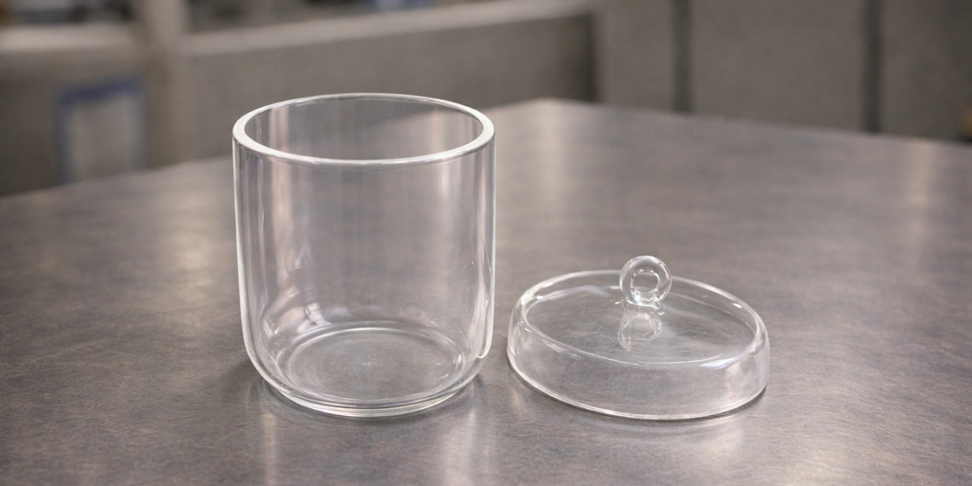
Beyond nominal wall thickness as a geometric output of OD and ID, uniformity of that thickness throughout the crucible body constitutes an independent and equally critical specification parameter — one that directly governs thermal stress distribution, mechanical load capacity, and service life under cyclic thermal loading. This distinction between nominal value and uniformity is frequently overlooked, with measurable operational consequences.
Minimum and Maximum Wall Thickness by Crucible Diameter
Wall thickness must satisfy two simultaneous boundary conditions: it must be thick enough to maintain structural integrity under thermal and mechanical loading, yet thin enough to avoid excessive thermal gradients across the wall section that introduce stress concentrations. The minimum permissible wall thickness scales approximately with crucible diameter at a ratio of 1:25 to 1:20 — meaning a 300 mm (12-inch) diameter crucible requires a minimum wall thickness of roughly 12 mm to 15 mm to sustain its own weight at operating temperature without viscous deformation.
For smaller crucibles in the 50–150 mm (2–6 inch) diameter range, minimum wall thicknesses of 3 mm to 6 mm are routinely achieved and are structurally adequate for operating temperatures up to 1,200°C. As diameter increases above 350 mm (14 inches), structural demands accelerate non-linearly: 18-inch crucibles typically carry wall thicknesses of 18–25 mm, and 22-inch variants used in large-diameter CZ pullers are commonly specified at 22–30 mm. Exceeding the maximum practical wall thickness — approximately 35 mm for most standard fusion forming processes — introduces thermal gradients during the forming stage itself that produce residual stress in the finished part.
These guidelines represent the output of decades of process refinement, and deviations from the standard thickness-to-diameter ratios carry documented risk. Cases where wall thickness was reduced by 15% below the recommended minimum to meet volume constraints have resulted in crucible collapse rates three to five times higher than baseline during the second and third thermal cycles, based on production tracking data from high-volume CZ operations.
Radial and Axial Thickness Variation Tolerances
Thickness uniformity is assessed along two independent geometric axes: radial uniformity (variation around the circumference at a fixed height) and axial uniformity (variation along the height at a fixed angular position). These two modes of non-uniformity arise from different aspects of the manufacturing process and have different consequences for crucible performance.
Radial thickness variation — measured as the difference between the maximum and minimum wall thickness values taken at equal angular increments around the circumference at mid-height — is typically specified as ≤ ±0.3 mm for crucibles below 200 mm diameter and ≤ ±0.5 mm for larger formats. Radial non-uniformity greater than these values produces an asymmetric thermal resistance around the circumference, creating a rotating thermal gradient within the melt that interferes with crystal pull stability in CZ growth. Axial thickness variation — measured from rim to base along a vertical line — reflects the tapering inherent in rotary forming processes. A controlled taper of 0.1 mm to 0.3 mm per 100 mm of height is acceptable and structurally benign; uncontrolled axial variation exceeding 0.5 mm per 100 mm indicates a forming defect.
Wall thickness is measured non-destructively using ultrasonic pulse-echo testing, with a measurement frequency of 5–10 MHz providing resolution of ±0.05 mm or better. This technique allows full-surface mapping without contact with the internal bore, preserving the acid-cleaned surface condition required for semiconductor-grade production.
How Wall Thickness Affects Thermal Stress Distribution
At the operating temperatures of silicon CZ growth (1,420–1,500°C), fused quartz transitions from a fully elastic solid to a visco-elastic regime where plastic deformation under sustained load becomes non-negligible. Within this regime, thermal stress is generated primarily by temperature gradients across the wall cross-section, and the magnitude of that gradient scales directly with wall thickness according to Fourier's law of heat conduction (q = −k · dT/dx)2.
For a fused quartz wall of thermal conductivity k ≈ 1.38 W/(m·K) exposed to a radial heat flux of 10 kW/m², a 10 mm wall sustains a through-wall temperature difference of approximately 72°C, while a 20 mm wall of the same material under the same flux sustains a gradient of 145°C. Given fused quartz's CTE of ~0.55 × 10⁻⁶/°C, the resulting differential thermal strain is ~0.008% across a 10 mm wall versus ~0.016% across a 20 mm wall. While these values appear modest, they act on a material with a relatively low fracture toughness (K₁c ≈ 0.75 MPa·m^0.5), meaning that even small differential strains at a geometric discontinuity — such as a wall thickness step or base junction — can initiate crack propagation.
Non-uniform walls amplify this effect disproportionately. A section where local thickness is 30% greater than the nominal value will sustain a thermal gradient 30% higher, creating a stress concentration at the boundary between thicker and thinner zones. Production data from semiconductor CZ operations indicate that crucibles with radial thickness variation exceeding ±0.8 mm have demonstrated a 40–60% reduction in cycle life compared to crucibles held within ±0.3 mm, all other parameters being equal.
Wall Thickness Specification Reference
| Crucible Diameter (mm) | Min Wall Thickness (mm) | Max Wall Thickness (mm) | Radial Variation Tolerance (mm) | Axial Taper Allowance (mm per 100 mm) |
|---|---|---|---|---|
| 50-100 | 3.0 | 8.0 | ±0.2 | ≤ 0.2 |
| 100–200 | 5.0 | 12.0 | ±0.3 | ≤ 0.3 |
| 200–350 | 10.0 | 20.0 | ±0.4 | ≤ 0.3 |
| 350–500 | 15.0 | 28.0 | ±0.5 | ≤ 0.4 |
| > 500 | 20.0 | 35.0 | ±0.6 | ≤ 0.5 |
Surface Finish Options for Quartz Crucibles
Surface condition is among the most consequential yet most frequently under-specified parameters in quartz crucible procurement — the finish applied to internal and external surfaces determines particle generation behavior, metallic contamination release, and adhesion characteristics during high-temperature service.
- Fire Polishing
In fire polishing, the crucible surface is exposed to an oxy-hydrogen flame at temperatures between 1,600°C and 1,700°C, causing a thin surface layer (approximately 50–200 μm) to re-flow and solidify into a smooth, crack-free skin. The resulting surface roughness is typically Ra ≤ 0.4 μm, compared to Ra values of 1.5–3.0 μm on an as-formed crucible. The re-flow layer also seals micro-cracks and surface pores that would otherwise act as nucleation sites for particulate detachment into the melt. Fire polishing does not alter the chemical composition of the bulk material, making it fully compatible with high-purity applications; however, it introduces a thin devitrified surface zone upon cooling, which must be accounted for in service-temperature specifications.
- Mechanical Grinding and Lapping
This approach produces a controlled, reproducible surface finish on features that require precise dimensional conformance — most commonly the rim face, flange contact surface, or external cylinder for press-fit or shrink-fit assemblies. Diamond wheel grinding achieves Ra values of 0.8–1.6 μm, while diamond lapping of flat contact surfaces can reach Ra ≤ 0,2 μm. The trade-off is the introduction of a subsurface damage layer extending 20–80 μm below the ground surface, within which micro-cracking from abrasive contact reduces local fracture toughness. Mechanical grinding is therefore restricted to surfaces not in direct contact with process media and is combined with a subsequent acid etch or fire polish step when the treated surface will be exposed to high-temperature environments.
- Acid Leaching (HF Treatment)
A controlled immersion in hydrofluoric acid solution (typically 5–10% HF by volume for 10–30 minutes) dissolves the outermost 5–20 μm of the quartz surface, along with any adsorbed metallic ions incorporated during grinding, handling, or prior furnace exposure. Post-leach surface metal concentrations are typically reduced by one to two orders of magnitude relative to the as-formed surface. HF-leached crucibles must be triple-rinsed in deionized water (resistivity ≥ 18 MΩ·cm) and handled with clean-room protocol to prevent recontamination before use.
- Coating Treatments — BN and Carbon
Boron nitride (BN) coatings, applied by spray or CVD deposition at 5–50 μm thickness, prevent the silicon melt from wetting and adhering to the quartz surface, which reduces the mechanical stress exerted on the crucible wall as the solidifying ingot contracts. Carbon (graphite) coatings serve a similar anti-sticking function in non-oxide melt systems. Both coating types introduce additional parameters: coating thickness uniformity (typically ±20% of nominal), adhesion strength, and chemical compatibility at temperature, all of which must be specified and verified independently of the substrate.
Surface Finish Comparison
| Treatment | Typical Ra (μm) | Metal Removal Depth | Maximale Betriebstemperatur (°C) | Primäre Anwendung |
|---|---|---|---|---|
| As-formed (unfinished) | 1.5-3.0 | Keine | 1,200 | Low-purity industrial |
| Feuerpoliert | ≤ 0.4 | Keine | 1,600 | Semiconductor, solar CZ |
| Mechanical Ground | 0.8–1.6 | None (adds damage) | Contact surfaces only | Rim, flange fit |
| Acid Leached (HF) | 0,8–1,5 | 5–20 μm | 1,650 | High-purity semiconductor |
| BN Coated | 0.5-1.0 | K.A. | 1,400 | Anti-sticking, CZ growth |
| Carbon Coated | 0.3–0.8 | K.A. | 1,600 | Non-oxide melts |
Structural Configurations Beyond Standard Cylindrical Shapes
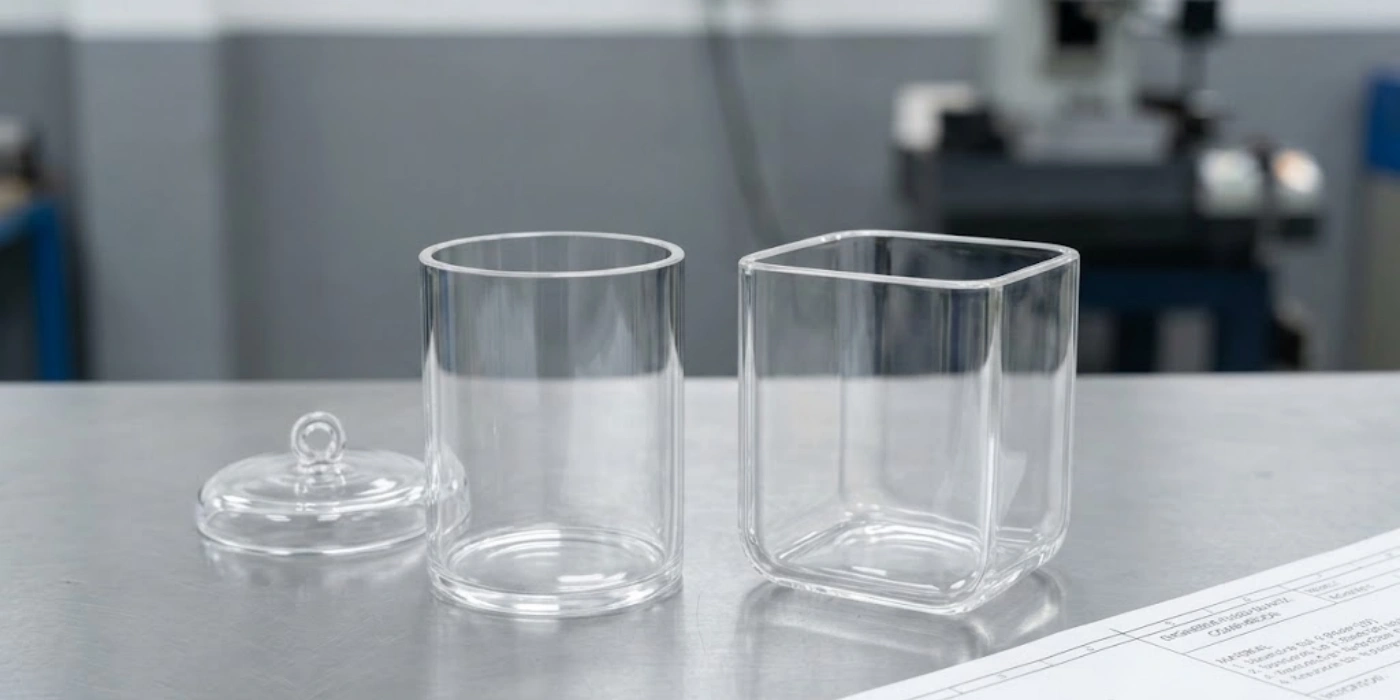
The cylindrical form accounts for the overwhelming majority of quartz crucible production volume, but a substantial and technically demanding subset of applications requires configurations that deviate fundamentally from this geometry. These deviations introduce an entirely distinct set of dimensional parameters — and the fabrication of customized quartz crucibles in non-cylindrical forms demands explicit specification of each additional variable, since the standard parameter set is insufficient to fully constrain the geometry.
Square and Rectangular Crucible Geometries
Square and rectangular quartz crucibles are specified primarily in applications where the process vessel or heating element geometry is itself rectangular — multi-zone diffusion furnaces, rectangular induction coil configurations, and square mold casting systems for polycrystalline silicon. The defining additional parameters are the internal length (L), internal width (W), the corner internal radius (r), and the wall thickness at both the flat face and the corner sections.
The corner radius r is not a decorative feature — it is a structurally mandatory parameter. An internal corner radius approaching zero creates a stress concentration factor (Kt) exceeding 3.0 at the corner, which in a material with fracture toughness K₁c of ~0.75 MPa·m^0.5 would result in spontaneous cracking upon the first thermal cycle. In practice, minimum internal corner radii are specified at 5 mm for crucibles with wall thicknesses below 8 mm and at 8–15 mm for heavier-walled rectangular forms. Wall thickness at the corner section typically increases by 10–20% relative to the flat-face nominal thickness to compensate for the geometric stress amplification at the bend.
Length-to-width ratios (L:W) for rectangular crucibles are constrained by the forming process. Aspect ratios above 3:1 introduce significant differential shrinkage during cooling that can bow the longer walls inward by 0.5–2.0 mm, introducing dimensional non-conformance in the finished part. For ratios above 4:1, internal forming cores or post-forming annealing fixtures are required to maintain flatness, both of which add to specification complexity and must be documented in the engineering drawing.
Tapered, Conical and Flanged Variants
Tapered crucibles — where the internal diameter changes progressively from base to rim — are characterized by the included taper angle (2α) measured from the central axis. For external draft-angle release geometries, taper angles of 1° to 3° (half-angle 0.5° to 1.5°) are standard; for functional tapers where the internal volume distribution is the design intent, half-angles up to 15° are produced. The critical parameter for any tapered design is the minimum wall thickness at the thinnest cross-section, which must satisfy the diameter-dependent minimum thickness criteria established in the wall thickness section above.
Conical crucibles, distinguished from tapered cylinders by the absence of a parallel-walled section, are fully defined by the included half-angle α, the base (apex) diameter or radius, and the rim diameter. Half-angles of 30° to 60° represent the most structurally viable range for fused quartz, as steeper cones (α < 30°) create excessively thin apex sections and shallower cones (α > 60°) approach a dish geometry that loses the compressive load-distributing benefit of the conical form. A truncated apex with a minimum flat diameter of 5–10 mm is standard practice.
Flanged crucibles add a horizontal annular shelf at the rim, fully defined by flange outer diameter (FOD), flange thickness (t_f), and the flange-to-wall junction radius (r_j). The junction radius is the most structurally sensitive parameter: an abrupt right-angle junction between flange and wall creates a bending stress concentration during thermal loading that frequently initiates rim fracture. A junction radius of at least 5 mm is the recommended minimum value; radii of 8–12 mm are preferred for crucibles subjected to repeated thermal cycling. Spout (pouring lip) variants introduce additional parameters: spout angle from vertical (typically 30°–60°), spout bore diameter, and spout length, all of which interact with the crucible's center-of-mass balance and must be specified relative to the primary axis.
Wall Angle Tolerances for Non-Cylindrical Geometries
In any non-cylindrical crucible, the angular orientation of the sidewall with respect to the crucible's central axis is a critical parameter that must be independently specified and verified, because it cannot be inferred from diameter measurements alone. Wall angle in tapered and conical forms is measured as the deviation of the actual wall surface from the nominal design angle, expressed in degrees or as a linear deviation per unit height (mm/100 mm).
For tapered cylindrical crucibles, wall angle tolerances are typically ±0.2° to ±0.5° from nominal; this corresponds to a dimensional deviation of ±0.35 mm to ±0.87 mm per 100 mm of height at the wall surface. An angular error of 0.5° in a 200 mm deep crucible translates to a rim diameter deviation of ±1.75 mm, which in a press-fit assembly may be sufficient to prevent correct seating. For rectangular geometries, wall angle is measured independently on all four faces and at each corner, since differential shrinkage during cooling can introduce different angular deviations on opposite faces of the same part.
Angular deviation of sidewalls directly affects thermal field symmetry in induction-heated systems, where the coupling efficiency between the conductive susceptor and the crucible depends on the parallelism of the outer surface and the coil geometry. A wall angle error of 1° on a 300 mm tall crucible creates a maximum air gap variation of ±2.6 mm between the crucible surface and a cylindrical susceptor, which, in a 2 kHz induction system, reduces local coupling efficiency by approximately 8–12% at the most deviant section.
Non-Cylindrical Geometry Parameter Summary
| Geometrie | Unique Parameters | Corner / Junction Radius Min | Wall Angle Tolerance | Max Viable Aspect Ratio |
|---|---|---|---|---|
| Square | L, W, corner radius r | 5 mm (thin wall) / 15 mm (thick) | ±0.3° per face | L:W ≤ 3:1 |
| Rechteckig | L, W, r | 8 mm | ±0.3° per face | L:W ≤ 3:1 |
| Tapered Cylinder | Half-angle α, ID_base, ID_rim | K.A. | ±0.2° to ±0.5° | K.A. |
| Conical | Half-angle α, apex geometry | Apex flat ≥ 5 mm dia. | ±0.3° | K.A. |
| Mit Flansch | FOD, t_f, junction radius r_j | 5 mm min / 8–12 mm preferred | ±0.2° at flange face | K.A. |
| Spout (Pouring Lip) | Angle, bore dia., length | 3 mm min at lip edge | ±1.0° | K.A. |
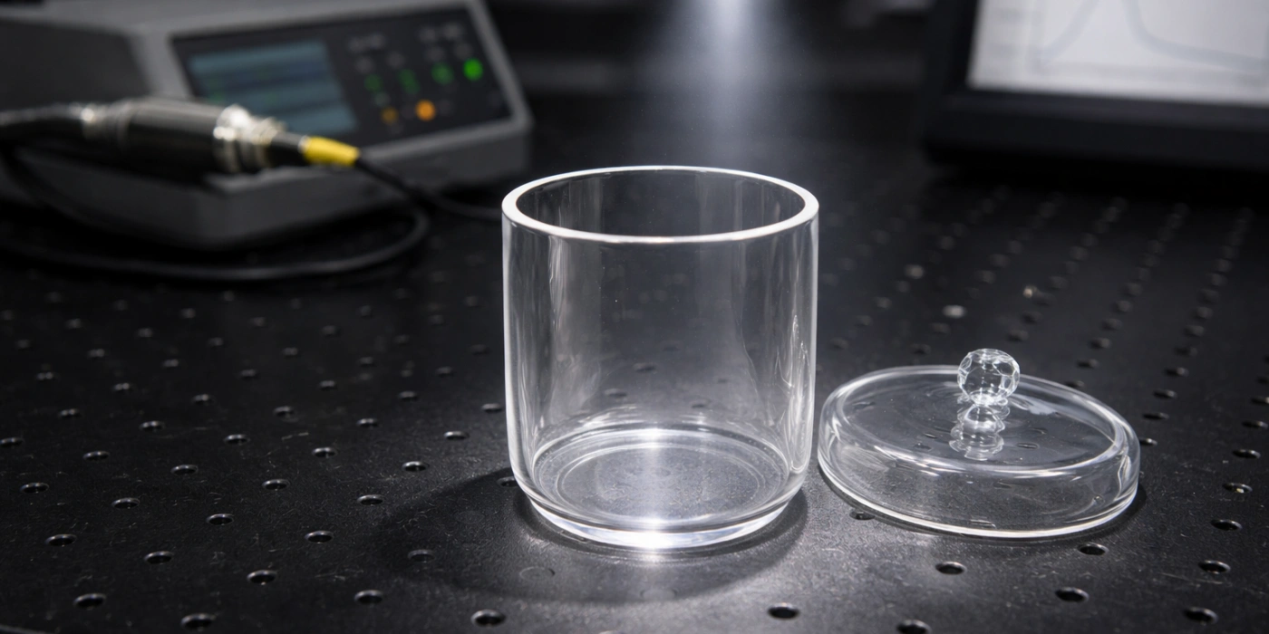
Optical Properties That Customized Quartz Crucibles Must Satisfy
Among all parameter categories, optical properties are unique to fused quartz and fused silica — no other crucible material (alumina, graphite, silicon carbide) carries specification requirements in this domain. For customized quartz crucibles operating in radiatively coupled furnace systems, these optical parameters are not secondary to geometry or purity: they are primary determinants of thermal coupling efficiency and, ultimately, of crystal quality.
Bubble and Inclusion Classifications in Fused Quartz
Gas bubbles and solid inclusions within the fused quartz matrix represent internal discontinuities that locally weaken the material, scatter thermal radiation, and — in the most severe cases — act as nucleation sites for fracture under thermal or mechanical stress. Bubble classification in quartz optical components is standardized under ISO 10110-7, which defines bubble grade as a function of the maximum permitted bubble cross-sectional area per unit reference area. Bubble diameters below 0,1 mm are typically not individually counted but contribute to a cumulative area budget; bubbles between 0.1 mm and 0.5 mm are counted discretely; bubbles exceeding 0,5 mm are cause for rejection in semiconductor-grade material.
Bubble density — the number of countable bubbles per unit volume — is the more operationally relevant metric for crucible material. Transparent fused quartz used in high-purity applications is typically specified at a bubble density of ≤ 5 bubbles/cm³ for bubbles ≥ 0.1 mm in diameter. Opaque (milky) fused quartz, by contrast, derives its opacity from a deliberately controlled high density of sub-100 μm bubbles — typically > 10⁵ bubbles/cm³ — introduced during the forming process to create an effective thermal radiation scatterer. This is a designed optical property, not a manufacturing defect.
Solid inclusions — crystalline particles, refractory contamination, or partially devitrified zones (Cristobalit3 stones) — are classified separately from gaseous bubbles. A cristobalite inclusion of 0.5 mm diameter in the wall represents a thermomechanical hazard: the SiO₂ cristobalite phase undergoes a displacive phase transformation at approximately 220°C during heating and cooling (β → α cristobalite inversion), accompanied by a ~4.9% volume change that generates localized compressive stress sufficient to initiate radial cracking from the inclusion site. Inclusions of cristobalite larger than 0.3 mm are cause for rejection in all temperature-cycling applications.
Transparency Versus Opacity Specifications for Different Applications
The distinction between transparent and opaque fused quartz is not merely a qualitative category — it is a quantitative specification defined by the material's infrared (IR) transmittance profile and its effective thermal emissivity at process temperature. Transparent fused quartz transmits approximately 90% of incident radiation at wavelengths between 0.2 μm and 3.5 μm, which spans the near-infrared emission spectrum of a silicon melt at 1,450°C. Opaque fused quartz, with its high internal bubble density, scatters this radiation, achieving an effective emissivity of 0.75–0.90 im Vergleich zu 0.10–0.20 for the transparent grade.
In the Czochralski silicon crystal growth process, the crucible performs a dual optical function. The outer surface must emit thermal radiation efficiently to the graphite susceptor, while the inner surface in contact with the melt must present a chemically stable, low-particle-release interface. Opaque crucibles, with their high emissivity, couple more efficiently with the radiative heat field from the susceptor, providing a more uniform temperature distribution at the melt surface. This is why virtually all commercial CZ silicon growth uses opaque (milky) quartz crucibles, typically with an inner transparent layer of 1–3 mm produced by a two-stage forming process.
In float-zone (FZ) silicon growth and in optical fiber preform deposition processes, the requirement is inverted: the crucible or tube must transmit focused radiation with minimal absorption and scattering losses. Transparent fused silica with bubble density < 1 bubble/cm³ and total internal transmittance > 88% at 1,064 nm (Nd:YAG laser wavelength) is specified for these environments. Substituting opaque material in such applications would absorb laser energy within the quartz wall, causing localized overheating and structural failure within seconds of exposure.
Optical Property Specification Reference
| Eigentum | Transparent Grade | Opaque (Milky) Grade | Two-Layer CZ Grade |
|---|---|---|---|
| Bubble Density (bubbles/cm³, ≥ 0.1 mm) | ≤ 5 | > 10⁵ (controlled) | Inner: ≤ 5 / Outer: > 10⁵ |
| IR Transmittance at 1–3 μm (%) | 85-92 | < 10 | Inner layer: 85–92 |
| Effective Emissivity at 1,450°C | 0.10–0.20 | 0.75–0.90 | Outer: 0.75–0.90 |
| Max Inclusion Size — cristobalite (mm) | ≤ 0.3 | ≤ 0.5 | ≤ 0.3 (inner layer) |
| Striae Permitted | None (critical optics) | Grade B allowed | Grade B (outer) |
| Primäre Anwendung | FZ, optical, laser | CZ silicon, solar | CZ silicon (300 mm) |
Thermal and Mechanical Properties Specified for Custom Orders
As the final material-level parameter category, thermal and mechanical properties represent the performance expression of all preceding specification choices — the geometry, purity, wall thickness, surface condition, and optical grade converge in determining how a crucible behaves under the thermal and mechanical loads of its service environment.
Maximum operating temperature is the most commonly cited thermal specification, but its value is not singular. Fused quartz maintains adequate structural rigidity for crucible applications up to approximately 1,050°C under sustained load for cylindrical forms at standard wall thicknesses. The material softening point — defined as the temperature at which viscosity falls to 10^7.6 Pa·s — is ~1,665°C for high-purity transparent fused silica and approximately 20–30°C lower for natural fused quartz of 4N purity. Short-duration peak exposures (< 5 minutes) up to 1,700°C are achievable without immediate structural collapse, but creep deformation accumulates measurably above 1,200°C under sustained mechanical loading.
Thermal expansion coefficient (CTE) for fused quartz is exceptionally low at ~0.55 × 10⁻⁶/°C across the 20–1,000°C range — approximately 8× lower than borosilicate glass and 30× lower than aluminum. This extraordinarily low CTE is the primary reason fused quartz withstands severe thermal shock: a crucible removed from a 1,200°C furnace and quenched in ambient air sustains a surface temperature drop of several hundred degrees with only modest thermal stress generation. The critical thermal shock parameter — the maximum temperature differential (ΔT_max) that a fused quartz wall can sustain without fracture — is approximately 350–500°C for a 10 mm wall, compared to < 100°C for most oxide ceramics of equivalent thickness.
Mechanical properties at room temperature establish the baseline structural capability of the crucible during handling and cold assembly. Fused quartz exhibits a Vickers hardness of ~570 HV, a modulus of rupture (flexural strength) of ~67 MPa, and a Young's modulus of ~72 GPa. These values degrade predictably at elevated temperature: at 1,000°C, flexural strength falls to approximately 50 MPa, and at 1,200°C it falls to ~35 MPa, driven by the onset of viscous relaxation. Fracture toughness K₁c of ~0.75 MPa·m^0.5 is low compared to engineering ceramics (alumina K₁c ≈ 3–4 MPa·m^0.5), which makes surface condition — particularly the elimination of surface micro-cracks — a primary determinant of actual service strength rather than the intrinsic material value alone.
Fatigue under cyclic thermal loading is the predominant failure mode in CZ crucible service, where each crystal pull cycle subjects the crucible to a temperature range of approximately 600°C. Empirical data from production environments indicate that standard 18-inch CZ crucibles achieve 1 to 3 growth cycles before devitrification and dimensional distortion reach levels that compromise crystal quality. Extended-life crucibles, achieved through tighter wall uniformity, higher purity grade, and two-layer construction, have demonstrated 4 to 6 cycles under controlled process conditions.
Thermal and Mechanical Properties Reference
| Eigentum | Wert / Bereich | Test Bedingung |
|---|---|---|
| Erweichungspunkt (°C) | ~1,665 (synthetic) / ~1,635 (natural) | Viscosity = 10^7.6 Pa·s |
| Max Sustained Service Temp (°C) | ~1,050 | Standard wall, cylindrical, structural load |
| CTE (×10⁻⁶ per °C) | ~0.55 | 20–1,000°C |
| Max Thermal Shock ΔT (°C) | 350–500 | 10 mm wall, water quench |
| Elastizitätsmodul (GPa) | ~72 | Room temperature |
| Flexural Strength — RT (MPa) | ~67 | 3-point bend |
| Flexural Strength — 1,200°C (MPa) | ~35 | 3-point bend |
| Vickers-Härte (HV) | ~570 | 1 kg load |
| Fracture Toughness K₁c (MPa·m^0.5) | ~0.75 | SENB method |
TOQUARTZ Custom Quartz Crucibles for Precision Applications
Across the full parameter landscape documented in this article — dimensional geometry, tolerance standards, material purity, wall uniformity, surface finish, structural form, optical properties, and thermomechanical behavior — the capability of the manufacturer to execute each specification with equal precision is the ultimate determinant of delivered performance.
TOQUARTZ produces customized quartz crucibles across the complete range of parameters described here. Dimensional capabilities extend from crucibles with internal diameters as small as 20 mm to large-format CZ-grade vessels exceeding 600 mm, with OD tolerances held to ±0,2 mm on precision orders. Material purity options span from standard 4N natural fused quartz through 6N and 7N+ synthetic fused silica, with full ICP-MS material certification available at the batch level. Wall thickness uniformity is maintained within ±0.3 mm radial variation for all semiconductor-grade production runs, verified by 100% ultrasonic thickness mapping prior to shipment.
Surface treatment capabilities at TOQUARTZ include fire polishing, precision mechanical grinding, HF acid leaching to semiconductor-grade cleanliness, and BN coating for anti-adhesion applications. Non-standard structural geometries — square, rectangular, conical, flanged, and spout variants — are produced with corner radii, wall angle tolerances, and flange planarity conforming to the values specified throughout this article. Optical grade is selectable between transparent, opaque, and two-layer CZ configurations, with bubble density certification available upon request.
Technical inquiries referencing specific parameter values, application temperatures, or process constraints are routed directly to engineering staff. Contact the TOQUARTZ technical team to initiate a specification review for your application.
Schlussfolgerung
The parameterization of customized quartz crucibles spans eight distinct technical dimensions, each operating as an independent variable with measurable consequences for process performance and service life. Dimensional specifications establish the geometric envelope; tolerance standards provide the measurement framework; purity grades determine contamination behavior at temperature; wall thickness uniformity governs thermal stress distribution and fatigue life; surface finish controls particle release and metallic contamination at the process interface; structural geometry beyond the cylinder introduces angular and form parameters with no equivalent in cylindrical specifications; optical properties define the material's radiative behavior; and thermomechanical properties set the service boundary conditions within which all other parameters must operate. Specifying these parameters with precision — and understanding the physical consequence of each — is the technical foundation of reliable high-temperature process performance.
FAQ
What is the minimum wall thickness for a customized quartz crucible at 400 mm diameter?
For a crucible in the 350–500 mm diameter range, the recommended minimum wall thickness is 15 mm, based on the 1:25 to 1:20 diameter-to-thickness structural ratio and the material's viscous deformation behavior above 1,200°C. Reducing below this threshold accelerates creep-induced dimensional distortion during high-temperature service.
What purity grade of quartz crucible is required for 300 mm silicon wafer CZ growth?
Advanced node 300 mm silicon crystal growth requires synthetic fused silica at 6N to 7N+ purity, with individual impurity limits of Fe ≤ 5–20 ppb, Na ≤ 5–10 ppb, and Ti ≤ 5–10 ppb, verified by ICP-MS batch certification. Natural fused quartz at 4N grade is not adequate for this application due to its inherently higher aluminum and alkali metal impurity content.
Why is wall thickness uniformity more important than nominal wall thickness in customized quartz crucibles?
Nominal wall thickness establishes the structural cross-section, but it is the uniformity — specifically radial variation ≤ ±0.3 mm and axial taper ≤ 0.3 mm/100 mm — that determines thermal stress symmetry within the crucible. Non-uniform walls create localized temperature gradients that concentrate stress at the boundary between thicker and thinner zones, reducing cycle life by 40–60% relative to crucibles held within tolerance, independent of the nominal thickness value.
What is the difference between transparent and opaque fused quartz in CZ crucible applications?
Transparent fused quartz transmits 85–92% of near-infrared radiation and has an effective emissivity of 0.10–0.20, making it unsuitable for CZ growth where high radiative coupling between the susceptor and melt is required. Opaque (milky) fused quartz achieves emissivity of 0.75–0.90 through a controlled high internal bubble density exceeding 10⁵ bubbles/cm³, enabling efficient radiative heat transfer into the melt. Commercial CZ crucibles typically use a two-layer construction combining a transparent inner liner with an opaque outer body to combine chemical purity with thermal performance.
Referenzen:
-
Inductively coupled plasma mass spectrometry is a high-sensitivity elemental analysis technique capable of detecting metallic impurities at sub-parts-per-billion concentrations, making it the standard verification method for semiconductor-grade quartz materials. ↩
-
Fourier's law of heat conduction describes the relationship between thermal flux and temperature gradient within a material, providing the quantitative basis for calculating through-wall temperature differences in high-temperature crucible applications. ↩
-
Cristobalite is a high-temperature polymorph of silicon dioxide that forms on the inner surface of quartz crucibles during prolonged thermal exposure, and its displacive phase inversion upon cooling generates localized mechanical stress that can initiate wall cracking. ↩