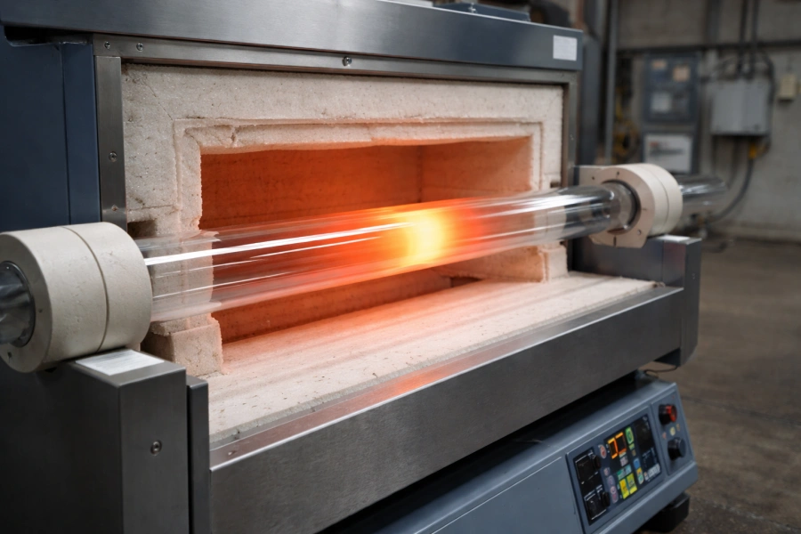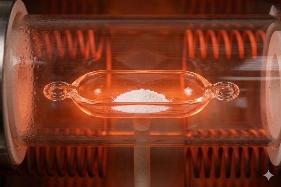
Quartz tubes fail without warning, and the consequences can be costly. The exact mechanisms behind high temperature quartz tube fracture must be understood before any failure can be prevented.
Every major cracking mechanism in fused quartz is dissected here — from instantaneous thermal shock to slow-onset devitrification, from molecular-level impurity damage to assembly-induced constraint stress. Each explanation is grounded in materials science and verified thermal data.
Quartz tube failure remains one of the most disruptive and least understood material problems across industrial furnace operations, semiconductor processing, and chemical vapor deposition environments. The cracking patterns observed in practice rarely result from a single cause; they emerge from the intersection of thermal physics, material chemistry, mechanical loading, and operational history. A structured understanding of how fused silica behaves — from the molecular scale upward — is required before any specific failure mechanism can be accurately identified.
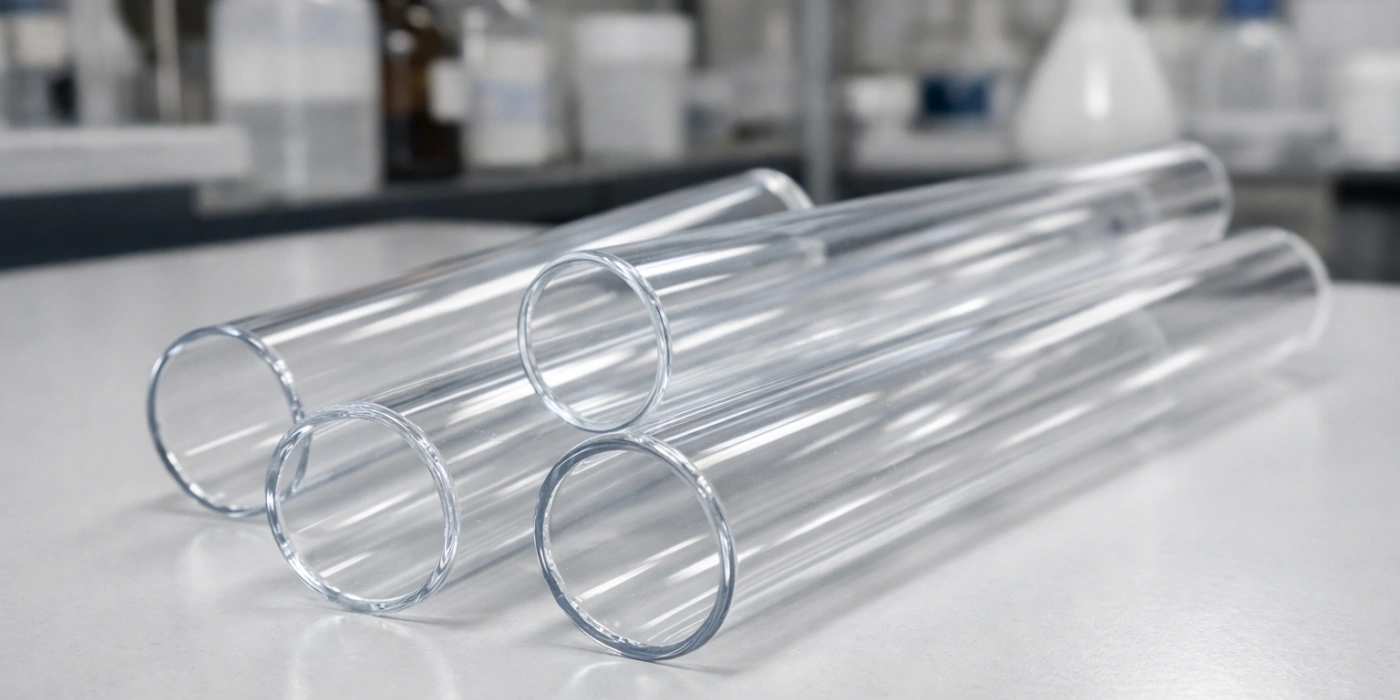
The Amorphous Silica Network in Fused Quartz
Fused quartz is not ordinary glass. Its fracture behavior under extreme heat is inseparable from its unique molecular architecture, making this foundation essential before any cracking mechanism can be accurately interpreted.
Fused silica consists of a continuous, three-dimensional random network of SiO₄ tetrahedra. Each silicon atom is covalently bonded to four oxygen atoms, and each oxygen atom bridges two silicon atoms, forming a disordered but highly cross-linked structure. Unlike crystalline quartz, which has a periodic lattice, fused quartz has no long-range order. This amorphous arrangement is responsible for its exceptionally low coefficient of thermal expansion (CTE) of approximately 0.55 × 10-⁶/°C — roughly 17 times lower than that of standard borosilicate glass.
This low CTE is the primary reason fused quartz can survive rapid temperature changes that would shatter conventional glass. However, the same amorphous network that confers this advantage also introduces vulnerabilities. The absence of a crystalline lattice means that structural defects — whether introduced during manufacture or accumulated during service — are not self-healing. Any localized disruption to the Si-O network, whether from impurity atoms, hydroxyl (OH) groups, or microscopic voids, creates zones of reduced mechanical strength. At elevated temperatures, viscous flow in the silica network begins to occur above approximately 1.050 °C, and the material transitions from a rigid solid toward a viscoelastic state. This transition does not prevent cracking; it merely changes the mechanism by which cracks propagate.
The mechanical strength of fused quartz at room temperature is approximately 48–55 MPa in tensile loading, but this value degrades significantly at temperatures above 1,100°C due to the onset of viscous relaxation. Furthermore, the surface condition of any Quarzrohr is critically important: fire-polished surfaces can sustain stresses far better than ground or abraded surfaces, where microcracks of 10–50 μm depth may already be present before the tube ever enters service. These pre-existing flaws act as stress concentrators, reducing effective fracture strength by a factor of two or more under thermal loading conditions.
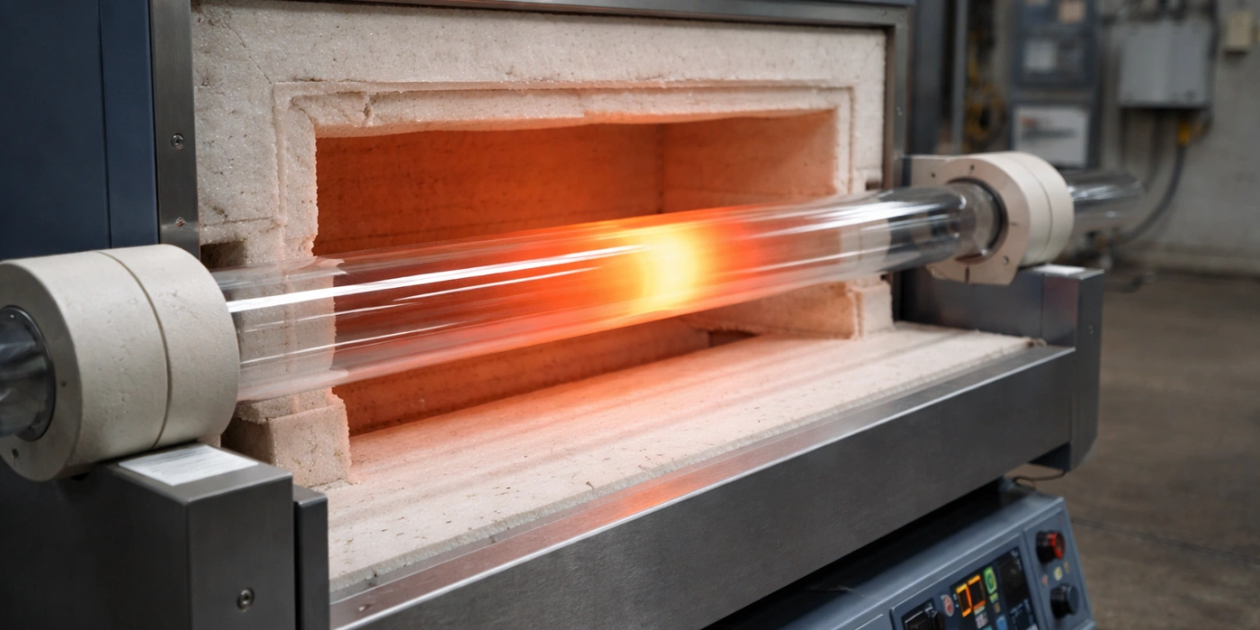
Thermal Shock in Quartz Tubes — The Primary Cracking Mechanism
Among all the failure modes documented in high-temperature silica components, thermal shock accounts for the greatest proportion of sudden, catastrophic fractures observed in service environments worldwide.
Thermal shock occurs when a temperature gradient develops across the wall or length of a quartz tube so rapidly that differential thermal expansion generates stresses exceeding the material's fracture strength. Because fused silica has extremely low thermal conductivity — approximately 1,4 W/m-K at room temperature — heat does not distribute uniformly through the tube wall during rapid heating or cooling events. The outer surface responds to temperature changes faster than the inner bore, creating a transient stress state that can rupture the tube within seconds. This mechanism is distinct from slow, steady-state thermal loading; it is defined entirely by the rate of temperature change and the resulting spatial gradient.
How Temperature Gradients Generate Internal Stress
The stress generated by a thermal gradient is governed by a well-established relationship in thermoelastic theory. For a cylindrical tube, the hoop stress (σ_θ) induced by a radial temperature gradient ΔT across the wall thickness can be approximated as:
σ_θ = E × α × ΔT / (1 − ν)
where E is the elastic modulus (~72 GPa for fused silica), α is the CTE (~0.55 × 10-⁶/°C), and ν is Poisson's ratio (~0.17).
Even a modest radial temperature difference of 200°C across a tube wall of 3 mm thickness can generate hoop stresses approaching 8–10 MPa. Although this appears well below the nominal tensile strength of fused quartz, the presence of surface microcracks amplifies local stress by a factor of 2–5× depending on crack depth and geometry. Consequently, effective fracture threshold under thermal gradient loading is far lower than static tensile test data would suggest.
The hottest surface — whether inner or outer — is placed in compression, while the cooler surface is placed in tension. Fused silica, like all brittle ceramics, is significantly weaker in tension than in compression. Its compressive strength exceeds 1,100 MPa, whereas its tensile strength rarely exceeds 55 MPa on a pristine surface and drops to below 25 MPa on a surface with pre-existing damage. This asymmetry explains why tensile cracks almost always initiate on the surface that is cooling most rapidly.
The fracture typically begins as a surface crack perpendicular to the axis of maximum tensile stress, propagating radially inward through the tube wall. In many documented cases involving rapid furnace loading, the crack front travels at velocities approaching 1,500 m/s — effectively instantaneous on a human timescale — leaving a characteristic conchoidal fracture surface typical of brittle silicate failure.
Critical Heating and Cooling Rates That Exceed Quartz Tolerances
Despite fused quartz's reputation for thermal shock resistance, it is not immune to rate-dependent fracture. Empirical data from tube furnace operations consistently identifies threshold heating and cooling rates beyond which failure probability increases sharply.
For standard-wall quartz tubes (wall thickness 2–4 mm), safe continuous heating rates are generally maintained below 5–10°C/min when the tube is loaded and positioned inside a furnace. Cooling rates are even more critical: forced air cooling or quenching into ambient air from temperatures above 800°C generates sufficient thermal gradients to cause immediate fracture in tubes with any surface damage. In practice, passive cooling at furnace-off conditions typically produces cooling rates of 3–8°C/min and is considered the safest regime for most standard tube configurations.
The most dangerous thermal events are not the highest temperatures, but the fastest transitions. Laboratory records from CVD and diffusion furnace operations show that the majority of tube fractures occur not during steady-state operation at peak temperature, but during the loading of cold samples into hot furnaces, or during abrupt power interruptions that allow uncontrolled cooling. A quartz tube that has survived hundreds of hours at 1,150°C may fracture in under 10 seconds if a room-temperature sample boat is introduced without a controlled pre-heating protocol.
Safe Thermal Ramp Rates for Fused Quartz Tubes
| Wanddicke (mm) | Max Heating Rate (°C/min) | Max Cooling Rate (°C/min) | Risk Temperature Range (°C) |
|---|---|---|---|
| 1.5-2.0 | 15 | 10 | >600 |
| 2.0–3.0 | 10 | 5 | >700 |
| 3.0-4.0 | 8 | 4 | >750 |
| 4.0–5.0 | 5 | 3 | >800 |
| >5.0 | 3 | 2 | >850 |
Localized Heating as a Hidden Source of Thermal Fracture
Not all thermal shock originates from furnace-wide temperature transients. Localized heating — affecting only a segment of the tube's length or circumference — is an equally destructive and far less recognized mechanism.
In tube furnace configurations, the transition zone between the heated region and the unheated tube extension can sustain axial temperature gradients exceeding 50°C/cm over a span of just a few centimeters. This gradient generates axial tensile stress in the cooler region adjacent to the hot zone boundary — a stress state that is particularly prone to initiating circumferential cracks that propagate around the tube's perimeter. These cracks often appear as clean, ring-shaped fractures at a fixed distance from the furnace end cap, which is a characteristic pattern that experienced furnace operators immediately recognize as gradient-induced failure.
Contact between the quartz tube and a localized heat source — such as a resistive heating element, an inductive coil, or even an unevenly wound furnace winding — creates circumferential hot spots that deviate the stress distribution from its symmetric state. Areas of the tube circumference that are closer to a heating element may be 80–120°C hotter than the diametrically opposite side, generating bending-mode thermal stresses that standard axisymmetric analyses do not capture. Finite element thermal models of horizontal tube furnaces with partially wound heating elements routinely show peak von Mises stresses1 at the tube's outer surface concentrated at these asymmetric heating zones.
Ceramic sample boats or supports in direct contact with the inner bore of a quartz tube create additional localized stress risers. Where a boat's edge contacts the tube wall, heat transfer is conductive and concentrated; the surrounding tube wall receives radiative heating at a lower rate. The resulting local temperature differential of 30–80°C across a contact zone of just 5–10 mm width is sufficient to initiate point-origin cracking that spreads outward in a characteristic star pattern.
Thermal Shock Cracking Mechanisms Summary
| Mechanismus | Stress Type | Fracture Origin | Typical Crack Pattern | Key Risk Factor |
|---|---|---|---|---|
| Rapid global heating | Hoop (tensile) | Outer surface | Axial crack | Aufheizrate |
| Rapid global cooling | Hoop (tensile) | Inner bore | Axial crack | Cooling rate |
| Hot zone boundary gradient | Axial (tensile) | Cooler zone edge | Circumferential ring crack | Gradient length |
| Localized element contact | Bending + hoop | Contact point | Star or radial crack | Asymmetric heating |
| Cold sample introduction | Radial gradient | Inner bore surface | Longitudinal split | Sample preheat protocol |
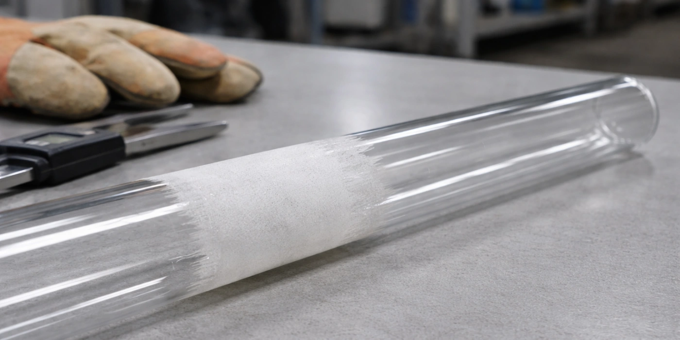
Devitrification and Its Destructive Effect on Structural Integrity
Where thermal shock produces sudden catastrophic failure, devitrification operates as a slow, cumulative process that silently undermines the structural integrity of fused quartz until a secondary stress event triggers final fracture.
Devitrification is the spontaneous crystallization of amorphous fused silica into crystalline phases — most commonly cristobalite (SiO₂ polymorph) — upon prolonged exposure to temperatures typically above 1.050 °C. This transformation is thermodynamically favorable because the crystalline state has lower free energy than the amorphous glass at elevated temperatures. The practical consequence for any high temperature quartz tube in continuous service is a progressive loss of homogeneity, optical clarity, and mechanical reliability across the tube wall.
The Phase Transformation from Amorphous Silica to Cristobalite
The devitrification process is a classical nucleation-and-growth phenomenon governed by classical solid-state kinetics.
Nucleation of cristobalite within fused silica requires an activation energy barrier to be overcome. At temperatures between 1,050°C and 1,200°C, nucleation rates are low but non-zero, meaning that long exposure times at these temperatures will eventually produce detectable crystalline zones. Above 1,200°C, the crystal growth rate accelerates dramatically, and visible milky-white crystalline patches can develop on tube surfaces within 10–50 hours of continuous exposure depending on purity and surface condition.
The growth of cristobalite does not occur uniformly through the tube wall. It initiates preferentially at the outer surface, where contaminants, surface damage, and atmospheric exposure provide nucleation sites unavailable in the pristine interior of the silica network. High-resolution X-ray diffraction studies of service-aged quartz tubes consistently show a crystalline surface layer 50–500 μm thick with a sharp transition back to amorphous glass beneath. This layered structure means that the mechanical mismatch between a crystalline outer layer and an amorphous interior develops progressively with service time, introducing interface stresses even in the absence of any external loading.
The transformation rate follows Arrhenius kinetics with an activation energy of approximately 200–250 kJ/mol for high-purity fused silica. This means that a 20°C increase in operating temperature roughly doubles the devitrification rate, a relationship that has significant implications for tubes operated near their nominal temperature limits.
The 200–270°C Inversion and Its Volume Change Consequences
The most mechanically destructive consequence of devitrification is not the crystallization itself but what happens during subsequent cooling.
Cristobalite exists in two polymorphic forms: β-cristobalite (stable above approximately 270°C) and α-cristobalite (stable below 200°C). As a devitrified quartz tube cools through this transition range, cristobalite undergoes a displacive phase transformation from β to α that is accompanied by a volumetric contraction of approximately 4.9%. This transformation occurs rapidly — within a narrow temperature window of roughly 200–270°C — and cannot be suppressed by slow cooling because it is a diffusionless, reconstructive transformation.
The volumetric mismatch between the contracting crystalline surface layer and the dimensionally stable amorphous core generates tensile stresses in the crystalline layer that routinely exceed the fracture strength of cristobalite, which is considerably lower than that of pristine fused silica. Fracture mechanics calculations based on a bilayer model — crystalline layer on amorphous substrate — predict tensile stresses in the surface crystalline layer of 15–30 MPa during the β-to-α inversion, values that consistently exceed the cracking threshold for crystalline SiO₂ phases. The result is a network of fine surface cracks appearing preferentially in the devitrified zone, which then serve as initiation sites for through-wall fracture under any subsequent thermal or mechanical loading.
In field observations, tubes that have operated for 200+ hours above 1,100°C frequently exhibit spontaneous fracture during routine cooling cycles that previously posed no risk — a direct consequence of the β-to-α inversion in accumulated cristobalite layers.
Surface Contamination as a Devitrification Accelerator
Devitrification in pure fused silica proceeds slowly enough that many industrial applications can tolerate extended service lives. However, surface contamination dramatically lowers the nucleation barrier and accelerates the entire crystallization sequence.
Alkali metal ions — particularly sodium (Na⁺) and potassium (K⁺) — are the most potent devitrification accelerators. These ions, which may originate from human skin contact (fingerprints contain approximately 10–100 μg/cm² of NaCl), from atmospheric dust, or from process chemicals, intercalate into the SiO₂ network and disrupt the bridging oxygen bonds that maintain the amorphous structure. Even a single ungloved hand contact with a quartz tube surface can introduce sufficient alkali contamination to trigger localized devitrification within 50–100 hours at temperatures above 1,000°C.
Water vapor presents a different but equally significant risk. At temperatures above 800°C, OH groups derived from atmospheric moisture or process gases react with strained Si-O-Si bonds at the tube surface, a process known as stress corrosion or static fatigue. This reaction lowers the effective surface energy of crack tips, reducing the stress intensity factor required for crack propagation by 20-40% compared to crack growth in dry conditions. Metal vapors — including those from tungsten, molybdenum, and iron-containing materials processed inside the tube — deposit on the inner bore and create compositionally distinct nucleation sites that initiate devitrification from the inner surface simultaneously with outer surface crystallization.
Devitrification Progression and Impact
| Service Temperature (°C) | Onset Time (hours) | Affected Zone | Volume Change at Inversion (%) | Surface Crack Risk |
|---|---|---|---|---|
| 1,000–1,050 | >500 | Outer surface only | ~4.9 | Niedrig |
| 1,050–1,150 | 100–300 | Outer 50–200 μm | ~4.9 | Mäßig |
| 1,150-1,200 | 50-100 | Outer 200–400 μm | ~4.9 | Hoch |
| >1,200 | 10-50 | Outer and inner surfaces | ~4.9 | Sehr hoch |
Thermal Expansion Mismatch between Quartz Tubes and Adjacent Components
Beyond the intrinsic material behavior of fused silica, a substantial proportion of quartz tube failures in real installations are attributable to the mechanical interfaces between the tube and the surrounding hardware — flanges, end caps, support structures, and sealing components.
Thermal expansion mismatch arises when dissimilar materials with different coefficients of thermal expansion are rigidly or semi-rigidly joined and then subjected to temperature change. For high temperature quartz tube assemblies, this is an almost universal condition because virtually every material used in furnace construction — stainless steel, Inconel2, alumina, graphite — has a CTE significantly higher than that of fused silica.
What Coefficient of Thermal Expansion Means for Quartz
The coefficient of thermal expansion quantifies how much a material's dimensions change per unit temperature rise, expressed in units of 10⁻⁶/°C (ppm/°C).
Fused silica's CTE of 0.55 ppm/°C is among the lowest of any engineering material, which is precisely why it is selected for high-temperature applications requiring dimensional stability. However, this low CTE becomes a liability when the tube must interface with components made of materials that expand significantly more upon heating. A 500 mm length of fused quartz tube will expand by only 0.28 mm when heated from 25°C to 1,025°C — a temperature rise of 1,000°C. Over the same temperature rise, a 316 stainless steel fitting of equivalent length would expand by 8,5 mm, a differential of 8.22 mm that the joint interface must accommodate or redistribute as stress.
The stress generated by this differential expansion is not absorbed elastically in a compliant system; instead, it concentrates at the stiffest point in the assembly — invariably the surface of the quartz tube. The relationship between differential expansion and induced stress depends on the elastic modulus of the constraining component and the geometry of the joint, but even modest constraint forces applied to the outer surface of a 50 mm diameter quartz tube can produce hoop stresses exceeding 10 MPa — approaching the effective fracture threshold for a surface-damaged tube.
CTE Comparison of Quartz and Common Assembly Materials
| Material | CTE (ppm/°C) | CTE Ratio vs. Fused Quartz | Typical Use in Tube Assemblies |
|---|---|---|---|
| Fused Silica (quartz) | 0.55 | 1.0× | Tube body |
| Alumina (Al₂O₃) | 8.1 | 14.7× | End plugs, support boats |
| 316 Stainless Steel | 16.0 | 29.1× | Flanges, end caps |
| Inconel 625 | 12.8 | 23.3× | High-temp fittings |
| Graphit | 4.0–8.0 | 7.3–14.5× | Susceptors, support rods |
| Mullite | 5.3 | 9.6× | Ceramic end seals |
Constraint-Induced Stress at Tube Ends and Flanged Joints
The geometry of the tube-flange interface determines the specific stress distribution imposed on the quartz surface and, consequently, the location and orientation of thermally induced cracks.
When a quartz tube is clamped between two rigid flanges with an O-ring or gasket seal, heating the assembly causes the flange material to expand radially at a much greater rate than the quartz tube. If the flange bore is a close fit to the tube outer diameter at room temperature, this differential expansion results in radial compression of the tube's outer surface by the flange bore — a condition that appears beneficial but is dangerous because it creates compensating tensile hoop stress in the tube wall interior. For a tube wall of 3 mm thickness under 5 MPa of radial external compression, the inner bore surface experiences tensile hoop stress of approximately 3–4 MPa, which, combined with process-related thermal gradients, can precipitate inner-bore crack initiation.
More commonly, the critical stress concentration occurs at the tube end face, where axial constraint from the flange prevents the tube from contracting freely during cooling. The axial tensile stress induced at the tube end face during cooling from operating temperature can be estimated from the differential thermal contraction and the axial stiffness of the flange assembly. For a steel flange constraining a 50 mm diameter quartz tube cooling from 900°C, axial tensile stresses at the tube end face can reach 12–18 MPa — values that, at a sharp tube edge with stress concentration factor Kt of 2–3, effectively generate local stresses of 24–54 MPa capable of initiating end-face cracking.
Joint Configuration and Crack Location
| Fugenart | Expansion Direction | Stress Concentration Location | Dominant Stress Mode | Crack Pattern |
|---|---|---|---|---|
| Close-fit rigid flange | Radial | Tube bore mid-wall | Tensile hoop (inner) | Axial, inner bore |
| Axially clamped end cap | Axial | Tube end face | Tensile axial | Circumferential end crack |
| Ceramic plug friction fit | Radial + axial | Tube ID near plug face | Combined biaxial | Ring crack at plug depth |
| Unsupported tube in guide | Lateral bending | Tube OD at contact point | Bending tensile | Longitudinal crack |
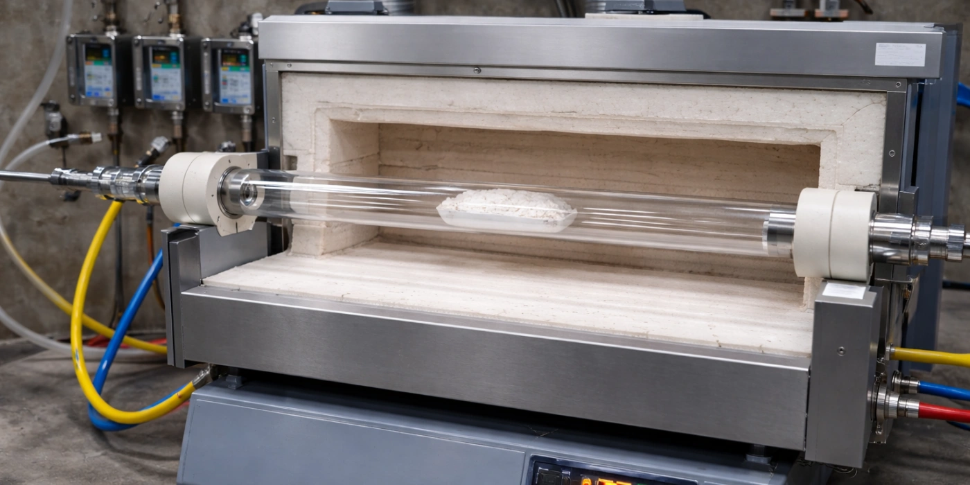
Mechanical Stress Concentrations That Initiate Cracks
Purely mechanical loading — independent of temperature gradients — represents a distinct and often underestimated pathway to quartz tube failure, one that becomes progressively more dangerous as operating temperature rises and material ductility decreases.
At elevated temperatures, the elastic modulus of fused silica decreases and viscous deformation begins to contribute to the total strain response. This viscoelastic behavior means that mechanical stresses applied at high temperature can produce time-dependent deformation — creep — that redistributes load concentrations rather than elastically storing them. Paradoxically, this makes high-temperature mechanical loading more insidious than room-temperature loading: creep deformation may appear to relieve stress initially, but the accumulated strain leaves permanent structural changes that lower fracture resistance during subsequent cooling.
Surface Defects and Micro-Cracks as Fracture Initiation Sites
The fracture behavior of fused quartz is governed to a significant degree by the Griffith criterion, which relates the critical stress for crack propagation to the size of pre-existing flaws in the material.
According to Griffith fracture mechanics, the fracture stress σ_f for a brittle material containing a surface crack of depth a is:
σ_f = K_IC / (Y √(πa))
where K_IC is the fracture toughness (~0.75 MPa·m^0.5 for fused silica) and Y is a geometric factor (~1.12 for a surface crack). A surface microcrack of just 25 μm depth reduces the local fracture stress to approximately 24 MPa — less than half the nominal strength of a pristine surface. Scratches introduced by abrasive contact, diamond cutting tools, or even alumina particles carried in process gas streams can create surface defects in this size range during routine handling and operation.
Scanning electron microscopy (SEM) fractographic analysis of failed quartz tubes from semiconductor diffusion furnace environments consistently identifies the fracture origin as a surface feature — a scratch mark, a chipped edge, a tool contact mark — rather than a bulk material defect. In one series of failure analyses involving 47 tube fractures across multiple furnace installations, 89% of fractures originated within 3 mm of a detectable surface discontinuity, confirming that surface integrity management is the most direct lever for controlling mechanically initiated failure.
The thermal environment amplifies this vulnerability. At temperatures above 800°C, stress corrosion (sub-critical crack growth driven by the reaction of water vapor with strained Si-O bonds at the crack tip) allows cracks to grow progressively under stresses well below the Griffith critical value. This mechanism — sometimes called static fatigue — means that a tube with a 25 μm surface scratch may survive initial loading but fail after hours or days of continuous service under a sustained stress that, at room temperature, would never cause fracture.
Bending and Point-Load Stress in Long Quartz Tubes under Heat
Long quartz tubes in horizontal furnace configurations experience gravitational bending loads that are often overlooked in standard installation procedures but consistently appear as contributing factors in failure analyses.
A horizontal quartz tube of 1,200 mm length, 60 mm outer diameterund 3.5 mm wall thickness has a self-weight of approximately 1.8 kg. Under simple beam theory with support at both ends, the maximum bending stress at the tube midspan due to self-weight alone is approximately 2.5 MPa. While this value is modest in isolation, it is additive to thermal stresses and, more critically, to stresses induced by the weight of sample boats loaded inside the tube. A ceramic sample boat loaded with 500 g of powder and positioned at the center of a 1,200 mm span increases midspan bending stress by an additional 3–4 MPa, bringing the combined mechanical stress to levels that interact dangerously with any pre-existing surface damage.
At temperatures above 1,000°C, fused silica enters the regime of viscous flow where creep strain accumulates under sustained loading. For a typical horizontal tube furnace operating continuously at 1,100°C, measurable midspan sag — permanent downward deflection due to creep — can develop within 500–1,000 hours of operation. This progressive deformation is not merely a dimensional change; it redistributes the stress state in the tube wall, creating tensile stresses on the outer (bottom) surface at the midspan that compound with thermal stresses and surface damage. Once permanent sag exceeds approximately 2–3 mm, the tube is considered mechanically compromised and is at elevated fracture risk during any subsequent temperature excursion.
Mechanical Stress Factors in Long Horizontal Quartz Tubes
| Parameter | Wert | Stress Contribution (MPa) | Fracture Risk Multiplier |
|---|---|---|---|
| Self-weight bending (1,200 mm span) | 1.8 kg tube | ~2.5 | 1.0× baseline |
| Loaded sample boat (500 g, center) | Additional load | +3.0–4.0 | 2.2–2.6× |
| Surface microcrack (25 μm) | Stress concentration | Effective strength ↓50% | ~2.0× |
| Operating at 1,100°C (creep onset) | Viscoelastic regime | Cumulative sag | Progressive |
| Combined loading at >1,000°C | All factors active | >8–10 MPa effective | Critical zone |
High-Purity Quartz versus Standard-Grade Tubes at Elevated Temperatures
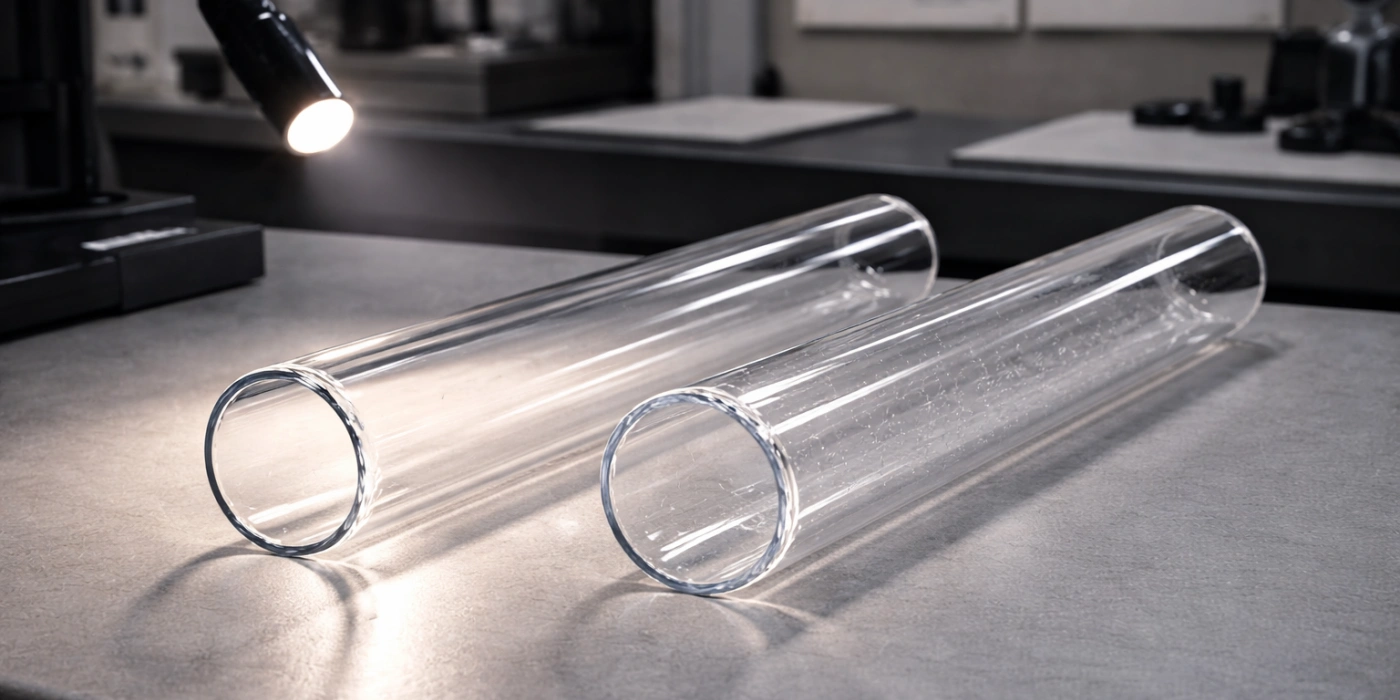
Not all quartz tubes sold under the same product description perform identically at high temperature, and the differences in fracture resistance between purity grades are far larger than most users anticipate when selecting tubing for critical applications.
The purity of fused silica — defined by the total concentration of metallic and non-metallic impurities in parts per million (ppm) by weight — directly determines both the temperature at which the material begins to soften and devitrify, and the density of structural defects that act as crack initiation sites. Impurity content is not a secondary specification; it is a primary determinant of service life under thermal loading.
How Impurity Content Weakens the Silica Network
The Si-O tetrahedral network of fused silica achieves its exceptional thermal and mechanical properties only when fully cross-linked and free from network-modifying impurity atoms.
Network-modifying cations — including Na⁺, K⁺, Ca²⁺, Al³⁺, and Fe³⁺ — occupy interstitial positions within the SiO₂ network and disrupt bridging oxygen bonds. Each non-bridging oxygen created by a monovalent modifier like Na⁺ reduces the overall cross-link density of the network, lowering the viscosity of the glass at a given temperature and shifting the softening point downward. For every 100 ppm increase in total alkali content, the effective softening point of fused silica decreases by approximately 5–15°C, and the temperature at which viscous creep becomes mechanically significant drops proportionally.
Hydroxyl (OH) groups, which are incorporated into the silica network during the manufacturing process, behave similarly. Synthetic fused silica produced by flame hydrolysis or chemical vapor deposition contains 100–1,200 ppm OH by weight, while electric fusion grades of natural quartz contain typically <5 ppm OH. High OH content lowers the viscosity of the glass network at elevated temperatures, accelerating creep and reducing the effective working temperature ceiling by 50–100°C compared to low-OH grades. Furthermore, OH groups act as nucleation sites for cristobalite formation, meaning that high-OH tubes are intrinsically more susceptible to devitrification at a given operating temperature.
Dissolved gas inclusions — predominantly microscopic bubbles of SO₂, CO₂, or inert gas trapped during manufacture — represent mechanical defects rather than chemical ones. A bubble of 50 μm diameter within a quartz tube wall acts as an internal Griffith flaw with an effective stress concentration factor of approximately 2, reducing the fracture strength of the surrounding material in the same manner as a surface microcrack of equivalent size.
Synthetic versus Natural Quartz Tubes and Their Fracture Resistance
The fundamental distinction in commercial quartz tubing is between material produced from natural quartz mineral feedstock and that produced by synthetic chemical processes, and this distinction has direct consequences for fracture behavior under thermal loading.
Natural quartz-derived fused silica, produced by electric melting of high-purity quartz sand or lump crystal, typically contains 10–30 ppm total metallic impurities and 1–10 ppm OH. This material is designated as Type I or II fused silica in the ASTM classification and is suitable for operating temperatures up to approximately 1,100°C for continuous service. Above this temperature, the residual impurity content becomes sufficient to accelerate devitrification and creep to rates that compromise structural integrity within a few hundred hours. Standard natural quartz tubes exhibit a softening point of approximately 1,665°C and a working point (viscosity of 10⁴ Pa·s) at around 1,530°C, but these headline figures apply only to pristine material unaffected by contamination or crystallization.
Synthetic fused silica (Type III and IV), produced by vapor-phase hydrolysis of SiCl₄ or by plasma fusion of high-purity silica powder, achieves metallic impurity levels below 1 ppm and offers dramatically superior resistance to devitrification and high-temperature creep. Tubes manufactured from synthetic material — commercially designated as GE 214, Heraeus Suprasil, or equivalent grades — can sustain continuous service at 1,200°C with devitrification onset times three to five times longer than natural quartz equivalents under identical contamination conditions. The trade-off is that synthetic grades contain higher OH levels (typically 150–1,000 ppm), which lowers UV transmission and modifies viscosity characteristics but does not compromise mechanical performance in the thermal ranges relevant to most furnace applications.
Fused Silica Grade Comparison for High-Temperature Tube Applications
| Eigentum | Type I (Natural) | Type II (Natural, OH-stripped) | Type III (Synthetic, high OH) | Type IV (Synthetic, low OH) |
|---|---|---|---|---|
| Total metallic impurities (ppm) | 20-50 | 10-30 | <1 | <1 |
| OH content (ppm) | <5 | <5 | 150–1.000 | <10 |
| Continuous use temp. (°C) | ~1,050 | ~1,100 | ~1,200 | ~1,200 |
| Devitrification onset (hrs at 1,100°C) | 50–150 | 100-250 | 300–700 | 300–700 |
| Bubble density (inclusions/cm³) | Höher | Mäßig | Niedrig | Sehr niedrig |
| Fracture toughness K_IC (MPa·m^0.5) | 0.72–0.75 | 0.73–0.76 | 0.74–0.77 | 0.74–0.77 |
Moisture, Atmospheric Contaminants and Quartz Tube Degradation
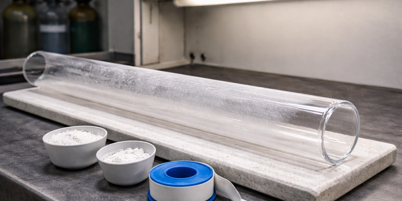
Chemical attack from the operating environment contributes to quartz tube degradation through mechanisms that operate in parallel with thermal and mechanical stress, often rendering the tube surface more vulnerable to all other failure modes simultaneously.
-
Water vapor and hydroxyl corrosion: At temperatures above 800°C, water vapor in the furnace atmosphere reacts with strained Si-O-Si bonds at the tube surface through the reaction Si-O-Si + H₂O → 2(Si-OH). This reaction, known as hydrolytic weakening, reduces the energy required to propagate a crack through the silica network by 20-40% because the newly formed Si-OH bonds at the crack tip are weaker and more easily displaced than bridging Si-O-Si bonds. In moist atmospheres (relative humidity >50% at room temperature translates to significant partial pressures of water vapor at elevated tube entry zones), the sub-critical crack growth rate can increase by more than an order of magnitude compared to dry conditions, dramatically shortening the time from crack initiation to through-wall fracture. Tubes used in steam-containing atmospheres or in processes involving water-bearing precursors are particularly susceptible, and their service life should be assessed against moisture-corrected fracture mechanics data rather than dry-condition specifications.
-
Alkali and metal vapor deposition: Many high-temperature processes — including the sintering of ceramic powders, the annealing of metal components, and the pyrolysis of organic precursors — generate volatile species that deposit on the inner bore of the quartz tube. Alkali oxides from ceramic binders, iron oxide vapors from steel annealing, and tungsten or molybdenum oxides from metal processing all deposit as thin films on the tube's inner surface. At operating temperature, these deposits react with the SiO₂ surface to form silicate phases with compositions and thermal expansion coefficients distinct from pure fused silica. Upon cooling, the thermal expansion mismatch between these silicate surface films and the underlying silica generates tensile stresses in the tube wall that can reach 5–15 MPa — sufficient to initiate surface cracking in combination with any existing damage. This mechanism is particularly insidious because the deposits are often invisible at operating temperature and only become apparent as discolored patches upon tube removal.
-
Acid and reducing atmosphere effects: Halogen-containing process gases — including HF, HCl, and Cl₂ used in semiconductor cleaning and deposition processes — attack the SiO₂ surface through volatilization3 reactions that progressively thin the tube wall. At 1,000°C, the etch rate of fused silica in a 10% HCl atmosphere is approximately 0.5–2 μm/hour, meaning that a tube in continuous halogen-containing service loses measurable wall thickness over hundreds of operating hours. This wall thinning is not uniform; it preferentially attacks zones of higher surface energy — scratches, devitrified regions, and grain boundaries — creating locally thinned areas where the effective stress under thermal loading is amplified by the ratio of nominal to residual wall thickness. Reducing atmospheres containing hydrogen at elevated temperatures can promote silica reduction at the surface, generating SiO vapor and leaving a porous, weakened surface layer with substantially reduced fracture strength.
Why Quartz Tubes Fail Faster with Repeated Thermal Cycling
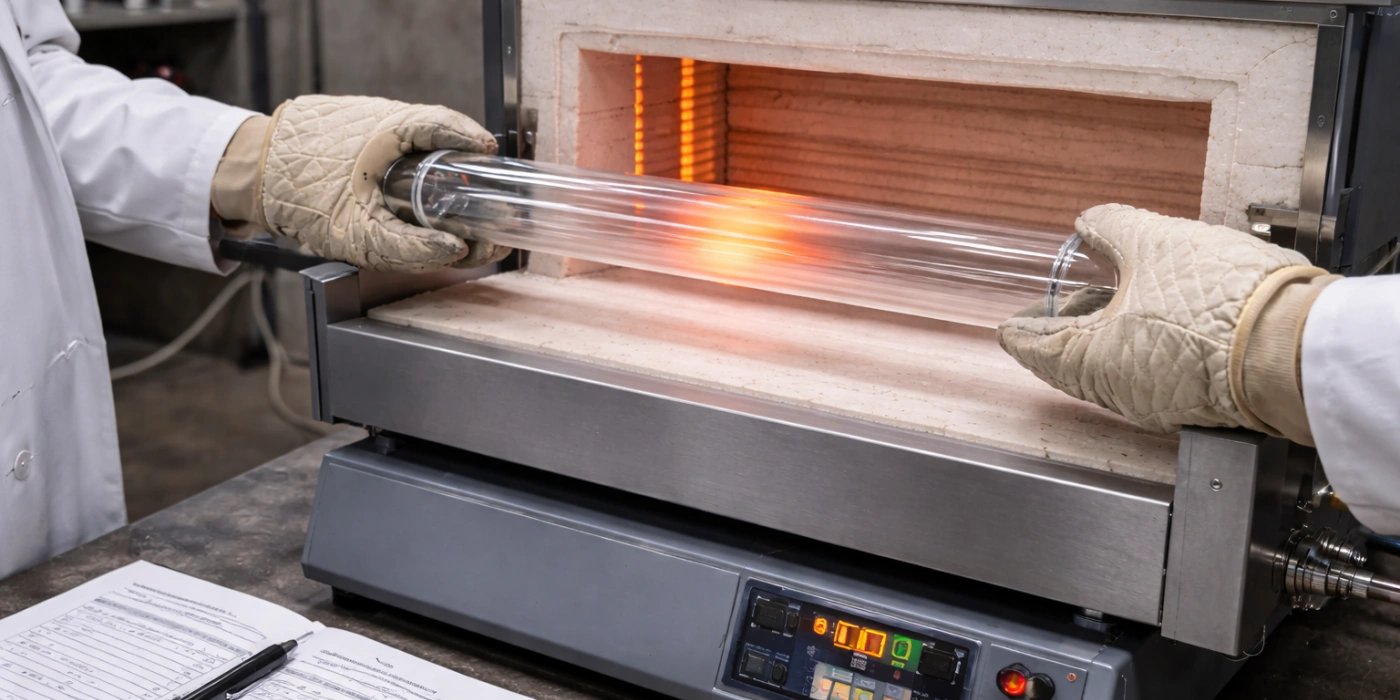
Cyclic thermal loading imposes a cumulative mechanical history on quartz tubes that no single-cycle analysis can capture, and understanding this history is essential for predicting when tubes that appear structurally sound will fail without apparent cause.
-
Fatigue crack accumulation mechanism: Unlike metals, which exhibit well-characterized fatigue behavior governed by dislocation motion, fused silica is a brittle material for which classical fatigue — in the sense of cyclically induced plasticity — does not apply. Nevertheless, thermal fatigue in quartz is real and well-documented, operating through the progressive extension of pre-existing surface microcracks during each thermal cycle. In each heating phase, tensile stresses on the cooler tube surfaces cause microcracks to open and extend incrementally. In each cooling phase, the same cracks close under compressive stress but do not heal — the crack tip has advanced slightly, and the effective flaw size has increased. After N thermal cycles, a surface crack that was initially 10 μm deep may have grown to 40–80 μm, reducing the local fracture stress by a factor of two or more and making the tube vulnerable to fracture under stresses that posed no threat on the first cycle. Data from tube furnace operations in academic and industrial settings indicate that the majority of quartz tube failures in multi-cycle operations occur between cycle 50 and cycle 200, corresponding to a crack growth regime where accumulated damage crosses the threshold for catastrophic fracture under routine operating stresses.
-
Devitrification-fatigue interaction: Repeated thermal cycling through the devitrification temperature range does not merely add cristobalite progressively; it also subjects the cristobalite layer that has already formed to repeated passes through the β-to-α inversion at 200–270°C. Each inversion cycle generates the same ~4.9% volumetric contraction, and the cracking damage introduced in the cristobalite layer during each cooling pass accumulates from cycle to cycle. What begins as microcracking in the crystalline surface layer after the first few cycles progresses, over 20–50 cycles, to a network of interconnected surface cracks that extends into the underlying amorphous silica. This mechanism explains why tubes that have been operating at 1,100°C for extended periods appear visually sound during inspection at operating temperature but fracture during a routine cool-down that they have survived many times previously — the β-to-α transition during that specific cooling event was the cycle that exceeded the accumulated damage threshold.
-
Creep-fatigue interaction in long-duration cycles: For processes that involve both high operating temperatures and long hold times at peak temperature — such as extended sintering or annealing runs lasting 8–24 hours — each thermal cycle also includes a sustained creep phase. Creep strain accumulated during each high-temperature hold is not fully recovered during cooling because fused silica does not exhibit significant reverse creep at lower temperatures. After multiple long-duration cycles, the cumulative permanent creep strain in the tube wall introduces a residual stress field that biases the tube toward tensile failure during subsequent heating. Finite element models of quartz tubes subjected to repeated 12-hour holds at 1,150°C predict that residual tensile stresses of 4–8 MPa develop in the tube wall after just 10 cycles, with these stresses concentrated at the outer surface of the midspan region — precisely where thermal shock and bending stresses are also highest.
Temperature Ratings and the Reality of Operational Limits for Quartz
Published temperature ratings for quartz tubes are frequently misapplied in practice because the relationship between the maximum temperature figures cited in datasheets and the actual safe operating conditions involves several material parameters that product specifications rarely explain in sufficient detail.
-
Softening point versus continuous use temperature: The softening point of fused silica — commonly cited as 1,665°C — is defined as the temperature at which the glass viscosity reaches 10^7.6 Pa·s, a value at which the material deforms measurably under its own weight within minutes. This figure is sometimes interpreted as the maximum operating temperature, an interpretation that leads directly to tube failure. The actual continuous use temperature for a horizontally mounted, load-bearing quartz tube is far lower: 1,050–1,100°C for standard natural quartz grades and 1,150–1,200°C for high-purity synthetic grades. Above these temperatures, creep deformation rates become mechanically significant over service timescales of hours to days. The gap between the softening point (1,665°C) and the continuous use limit (1,100°C) — a difference of more than 500°C — represents the single most commonly misunderstood aspect of quartz tube selection.
-
Annealing point, strain point, and their operational significance: Below the softening point, two additional thermal transition temperatures govern the mechanical behavior of fused silica. The Glühpunkt (~1,140°C for standard fused silica) is defined as the temperature at which residual stresses in the glass are relieved within approximately 15 minutes — the viscosity at this point is 10^12 Pa·s. Paradoxically, operating a quartz tube at or above its annealing point is not a sign of safety; rather, it means that thermal stresses induced by temperature gradients are being viscously relaxed rather than elastically stored. When the tube is subsequently cooled, this relaxed state means the tube has effectively been stress-relieved into a distorted shape, and the re-application of thermal gradients during the next cycle encounters the tube in a geometrically altered condition. The Dehnungspunkt (~1,070°C) marks the temperature below which residual stress relief becomes negligibly slow (requiring hours or days), and below which the tube can be considered a linearly elastic solid. Operating consistently below the strain point is the only regime in which standard thermoelastic fracture mechanics analyses apply accurately.
-
Short-term versus long-term temperature limits: Material datasheets frequently cite both a short-term maximum temperature (often 1,200°C for standard natural quartz) and a continuous use temperature that is 100–150°C lower. This distinction reflects the kinetic nature of devitrification and creep: both processes are time-dependent, meaning that brief excursions above the continuous use limit — lasting minutes rather than hours — do not immediately cause structural failure. However, each short-term excursion above the continuous use limit contributes incrementally to the accumulated devitrification and creep damage, reducing the tube's remaining service life in proportion to both the temperature excess and the duration of the excursion. A tube rated for 1,100°C continuous use that regularly experiences 1,200°C peaks during sample insertion events will exhaust its useful service life in a fraction of the time predicted by steady-state operating conditions alone.
Schlussfolgerung
The fracture of a high temperature quartz tube is rarely the product of a single event. Across the mechanisms examined in this article — thermal shock, devitrification, expansion mismatch, mechanical stress concentration, purity-related weakness, chemical attack, fatigue accumulation, and temperature rating misapplication — a consistent pattern emerges: failure results from the convergence of multiple factors that individually fall below critical thresholds but collectively exceed them. Recognizing which mechanisms are active in a given installation requires systematic analysis of material grade, operating temperature history, atmosphere composition, assembly geometry, and thermal cycle profile. The material science of fused silica is well characterized, and the physics of its failure modes is well understood. Applying that understanding to specific operating conditions is the technical foundation for extending tube service life and preventing unplanned process interruptions.
FAQ
Why does a quartz tube crack immediately when a cold sample is inserted into a hot furnace?
Inserting a room-temperature sample into a furnace at operating temperature creates an instantaneous radial temperature gradient across the tube wall in the vicinity of the sample. The inner bore, cooled by contact with the cold sample and its carrier gas, contracts while the outer wall remains at furnace temperature. The resulting tensile hoop stress on the inner bore surface, amplified by any pre-existing surface microcracks, can exceed the local fracture strength within seconds of sample introduction — producing a rapid, longitudinal split along the tube axis.
What is the white cloudy zone that appears on a quartz tube after extended high-temperature use?
The milky-white, opaque zone that develops on quartz tube surfaces after prolonged operation above approximately 1,050°C is cristobalite — a crystalline polymorph of SiO₂ produced by devitrification. This zone is mechanically weaker than the surrounding amorphous silica and undergoes a displacive phase transformation at 200–270°C during cooling, producing a volumetric contraction of approximately 4.9% that generates surface cracking. Tubes displaying visible devitrification zones are at elevated fracture risk during any subsequent thermal cycle.
Does a higher-rated maximum temperature on a quartz tube specification mean it will crack less easily?
Not necessarily. The maximum temperature cited in product datasheets typically refers to the softening point or short-term peak temperature, which can exceed the continuous use temperature by 500°C or more. A tube operated at its short-term maximum rating will devitrify and creep rapidly, accumulating damage that makes it increasingly susceptible to fracture over time. The continuous use temperature — the rating relevant to sustained operation — is the figure that governs real-world fracture resistance, and this value is significantly lower than the headline maximum.
Why do quartz tubes sometimes crack during cooling even after surviving the full heating cycle without damage?
Cracking during cooling rather than heating is a characteristic signature of two mechanisms: the β-to-α cristobalite inversion at 200–270°C (if devitrification has occurred), and constraint-induced axial tensile stress at the tube ends as the flange or end cap assembly prevents free thermal contraction. In both cases, the stress state that causes fracture is tensile and develops only upon cooling. A tube that survives the heating phase intact may nonetheless carry devitrified surface layers or residual constraint stresses that become critical only when the temperature passes through these specific transition ranges during the cool-down.
Referenzen:
-
Von Mises stress is a scalar measure used in structural engineering to predict yielding and fracture onset under complex multi-axial loading conditions. ↩
-
Inconel is a family of nickel-chromium superalloys widely used in high-temperature engineering applications where oxidation resistance and mechanical strength are simultaneously required. ↩
-
Volatilization in high-temperature chemistry refers to the conversion of solid surface material into gaseous products through thermally activated chemical reactions, resulting in progressive material loss. ↩